
By Dan Bettenhausen, Director of Mechanical Engineering
The design of double skin facades (DSFs) has evolved significantly in recent decades. Currently, demand exists for systems that harness the established benefits of these designs, such as improved acoustic performance and energy efficiency, while still conforming with traditional construction practices, which dictate that units should be fabricated and installed as individual unitized assemblies. This article explores the unique design process required to realize these systems.

Photos above courtesy of Will Pryce via Rafael Viñoly Architects
Acoustic Design
Enhancing the acoustic performance of the building envelope is commonly the principal motivation to employ a double facade system instead of a traditional single-leaf design. This approach is a natural consequence of the physical limitations associated with insulated glazing units, which are limited in size by practical constraints such as the availability of edge spacer assemblies, logistics associated with shipment and handling of materials, and other tenants of curtainwall design, which would be disrupted by extremely wide glazing assemblies. Thus, glass manufacturers rarely produce insulated assemblies with air spaces larger than one inch. This limitation is at odds with what acoustic theory and common test standards require to achieve enhanced sound attenuation. The mass-air-mass resonance predicted by acoustic theory for an insulated glazing unit decreases as the air cavity increases. A common strategy employed in the acoustic design of DSF systems is to tune this frequency to fall below the test band associated with ASTM E90-based metrics such as Sound Transmission Class (STC) and Outdoor Indoor Transmission Class (OITC). This practice improves ratings and results in sound transmission that is less perceptible. Since the width of the air cavity required to achieve this aim commonly exceeds three inches, the approach can only be realized with a DSF.
The paramount challenge associated with designing these systems is estimating the specific performance values that will be achieved by a given design since ratings such as OITC and STC are determined by testing, and project-specific materials are not available during the early phases of a project. This difficulty is compounded when considering the glazing deployment for a cavity wall system since values determined for existing systems are commonly not of similar construction, especially if the responsible trade contractor has limited experience with cavity wall designs. It is well known that most glass fabricators provide tables of test data for common insulated glass make-ups that aid in predicting the acoustic performance of single-leaf systems. To overcome this challenge, Enclos stands ready to assist by reviewing records from previous jobs, providing theoretical estimates, and determining an appropriate test schedule based on available materials to ensure that performance values are reasonably well-known before specific project materials are released for production.
Thermal Design
Cavity wall designs commonly achieve lower U-factors than traditional wall systems due to the insulating qualities of the air cavity created by the added glazing layer, which has a direct effect of reducing heat transfer through the wall and provides a secondary benefit by sheltering a portion of the interior framing from the building interior that would otherwise be directly exposed to space conditioning. Engineering standards for thermal transmittance, such as NFRC 100, are applicable for quantifying values associated with cavity wall systems in the same manner that conventional systems would be analyzed. While the reduced U-factor achieved is clearly a benefit, care must be taken when evaluating these systems to mitigate risks associated with internal condensation and the potential for heat build-up due to solar loads.
Systems erected in cold climates are more prone to develop condensation than those in warmer climates if no active means of condensation control are implemented. The most common type of active system utilizes pressurized air supply lines to condition each cavity wall unit with desiccated air. Alternatively, in milder climates, it may be sufficient to provide access to the facade cavity for periodic cleaning through an operable inner leaf or allow the cavity to remain sealed if cavity temperatures never fall below the interior dew point.
Routine analysis using conventional engineering software often miscalculates cavity temperatures. Enclos utilizes Computational Fluid Dynamics (CFD) modeling to account for stratification and air motion within the facade cavity.
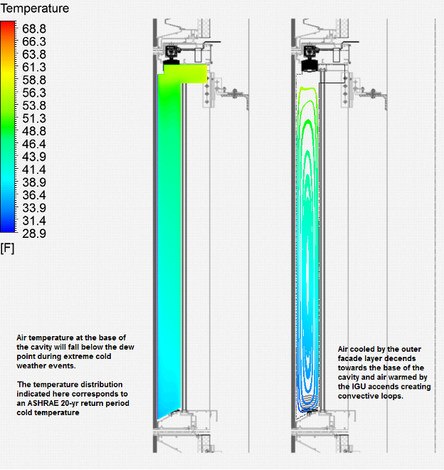
While most cavity wall designs reduce solar gain, the temperature of internal components is often significantly elevated. In particular, opaque elements such as motorized Venetian blinds may promote heat buildup and need to withstand higher service temperatures. Glass makeups must also be evaluated to ensure they are appropriate for a given application. Enclos can assist in verifying the suitability of project materials by coordinating specified environmental loads and attentively analyzing them with manufacturers to aid in selection.
Mechanical Design
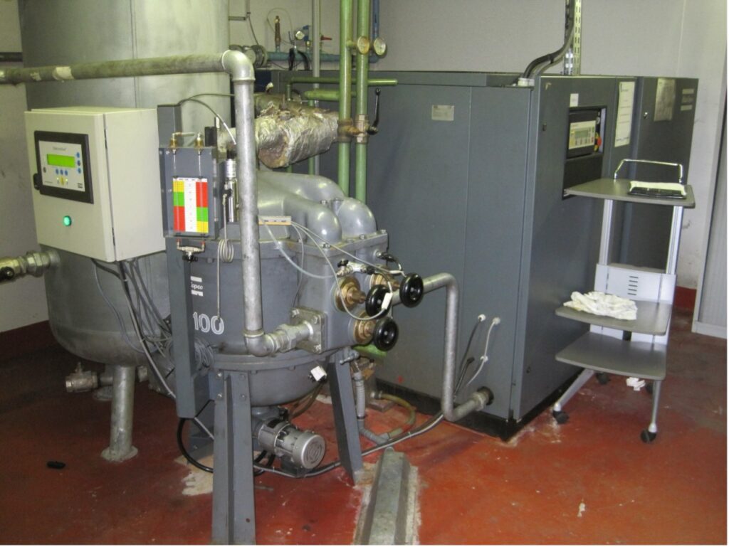
Implementation of active humidity control through air distribution requires additional trade coordination between Mechanical Equipment and Plumbing (MEP) and envelope sub-contractors, including specification of air supply requirements, design of the distribution system, and integration of its components with the overall building design, interface of individual facade units with the pressurized system, and system commissioning. Early in the project’s testing phase, the air supply rate is determined by considering the various rates of leakage that may occur between the facade cavity and the humidified building interior. This may require testing of gasket interfaces if the interior leaf is dry-glazed or includes operable components. Once a value is established, psychrometric analysis is employed to determine the supply rate of dry air needed for each facade cavity. These inputs are considered with pathways for egress from the cavity to establish mechanical settings. Other specifications may be appropriate to safeguard against noise and excessive pressurization. The design of the building’s mechanical equipment rooms must include pad space for compressors and dehumidification equipment, and other operational parameters such as requirements for make-up air, power, sound attenuation, and system maintenance must be considered. The air distribution is commonly fed through risers and distributed at each floor level in a perimeter loop configuration. The architectural design of the building must consider access at each facade unit for final hook-up, pressure regulation, and future access to these components.
Performance Testing
In some cases, testing of cavity wall systems may exceed conventional performance mockup requirements since traditional test sequences do not include provisions for evaluating the air supply system and the effect of its settings on condensation resistance. In fact, testing of this nature is not regulated by recognized industry standards in the United States. The infiltration rate of humid air into each enclosure may depend not only on interior humidity levels but also on internal pressurization of the building by HVAC systems. Testing these parameters with fidelity requires coordination with laboratories to ensure that existing facilities can be utilized in a manner that provides meaningful results.
Testing is not necessarily confined to verification efforts. The design of the system might require establishing the performance parameters of individual system components such as gaskets and orifices to determine how the rate of flow through these elements corresponds to system pressures. This information is required to evaluate the system’s total performance.
Manufacturing
Since it is common for cavity wall units to be sealed during manufacturing, care must be taken to ensure that interior surfaces are carefully handled. Intuitively, glass lites must be thoroughly cleaned and inspected for residue, lint, and other contaminants that cannot be easily removed after fabrication. This includes any loose materials, such as extraneous fasteners or debris from fabrication. If the assemblies include integral components, such as blinds, consideration is owed to how those components are tested before installation, cleaned, and secured during bunking. Less intuitive considerations include the potential for system components such as gaskets, power cups, and other sources to impart “memory” on the glass. Memory can be defined broadly as the propensity for condensation, dust, and other contaminates to form unevenly within the facade cavity over time, resulting in obvious distortions such as the appearance of rings or streak marks.
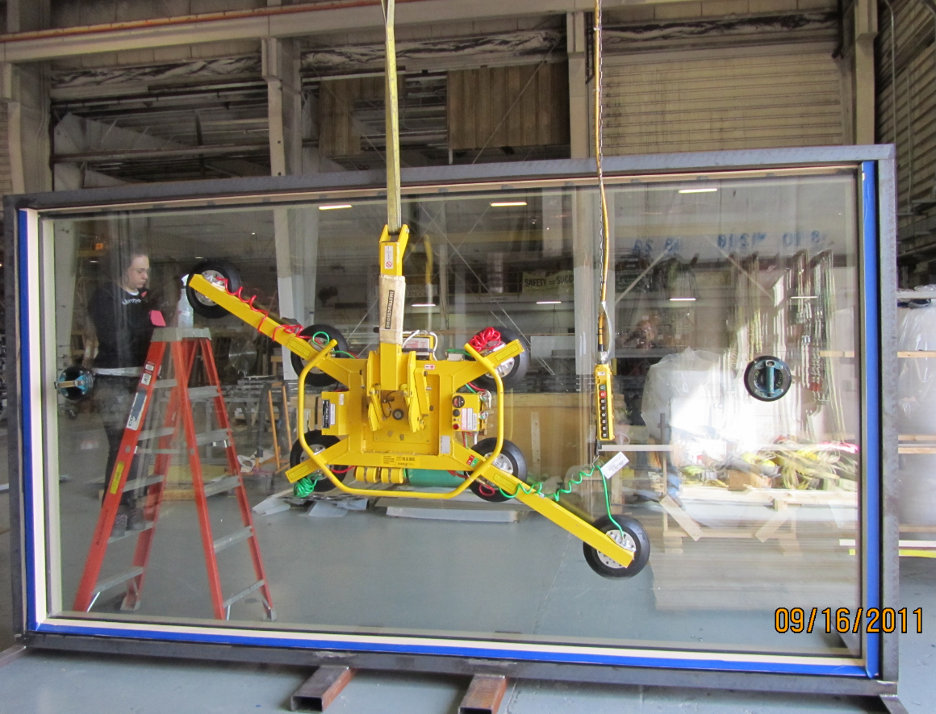
Storage and Handling of Unitized Assemblies
When cavity wall systems employ supplied air to mitigate condensation, it is important to consider how humidity will be controlled during storage, shipment, and installation. In extreme cases, more than a year might pass between when a unit is sealed and “hooked up” to air on-site. Care must be taken to coordinate trades to minimize this downtime to the greatest degree possible. Furthermore, potential conditions which might result in condensation should be carefully analyzed. If the environmental conditions pose a risk for condensation at any point, a mitigation strategy should be implemented. This can be achieved by installing temporary mechanical equipment or sealing the units with desiccant bags in an accessible location.
The risk of water infiltration should also be carefully assessed, especially if unitized assemblies will be stored outdoors and especially if both internal and external lites are not sealant-glazed. Attention is owed to the orientation of units in bunking, and temporary protection may be required to secure against potential infiltration points.
Loose elements within the facade cavity, such as mechanical shades, may need to be restrained to prevent accidental deployment or damage. If temporary fixtures are included within the assembly, a plan for on-site commissioning is required. Mechanical fasteners secured within the fixture should be secured against vibration if they could come loose and fall within the cavity.
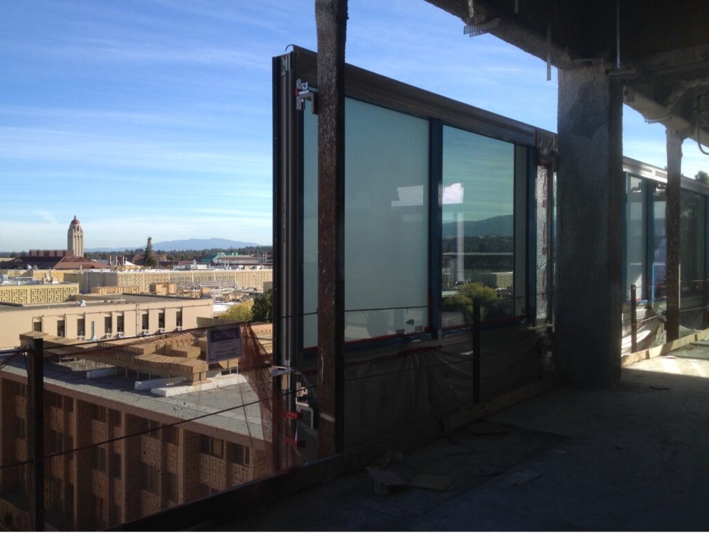
Site Installation
Special care must be taken with installed units since remediating any contamination within the facade cavity will be particularly burdensome since the assembly cannot be manipulated, and access may be hindered by other facets of work within the building. Additionally, the climate on-site may vary greatly with units exposed to weather and the interior of the building semi-conditioned. Installed units are susceptible to debris, spills, and water from the floor above. Fine dust from installed drywall, metalwork, and other sources complicates any activity requiring access to the facade cavity, especially if it is required to replace internal system components such as blinds or perform other remedial work. Special trade coordination may be required on-site to sequence these activities to minimize the risk of contamination.
Building Commissioning
A commissioning plan for each facade unit is required once the building is closed in and may include provisions such as testing motorized blind assemblies, verifying the operation of operable hardware, and connecting each cavity wall unit to the air supply system if it is used. The MEP contractor will furnish procedures for purging the system and adjusting the flow rate at each supply line to verify conformance with the specified parameters of the system. At that time, the air supply is attached to each facade cavity. As described, it is important to consider the location of the access port and ensure that plans for interior finishes are conducive to maintaining the system over time.
Conclusion
The design, fabrication, installation, and commissioning of cavity wall systems require detailed planning to ensure that building envelope systems are well coordinated with the architectural design of the building and its mechanical systems if needed to mitigate the risk of internal condensation. During the project’s design phase, care should be taken to analyze the proposed system based on the unique environmental conditions inherent to a given job using enhanced thermal modeling. Strategies for facade maintenance and conditioning can then be developed in tandem with other aspects of the building. If the motivation for employing a cavity wall system is to achieve a high level of acoustic performance, a test plan should be put in place to establish the performance of proposed glass configurations before designing system-specific components. Once the envelope system design is finalized, special steps are required during manufacturing, storage, and in the field to ensure that the internal cavity remains free from contamination, water infiltration, and excessive fogging. Trade coordination is required to bring building mechanical systems online as early as possible if the air supply is employed. Building commissioning includes integrating mechanical systems and testing any internal system components, such as motorized blinds.