by Earl Patrick, Enclos Director of Design
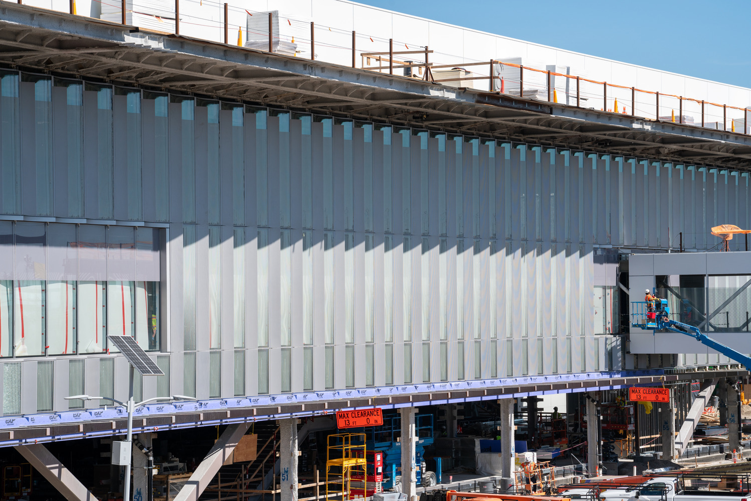
The curvilinear and luminous facade for the headhouse at the San Diego Airport Terminal 1 replacement is the culmination of a multitude of iterations and design studies led by James Carpenter Design Associates (JCDA), Gensler, Walter P. Moore, Starq & Enclos. We are proud of our role in providing early budget feedback and engaging in a collaborative design-assist project with the architectural team, ultimately delivering a world-class facade for the people of San Diego and those who travel there.
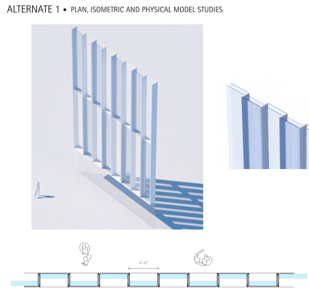
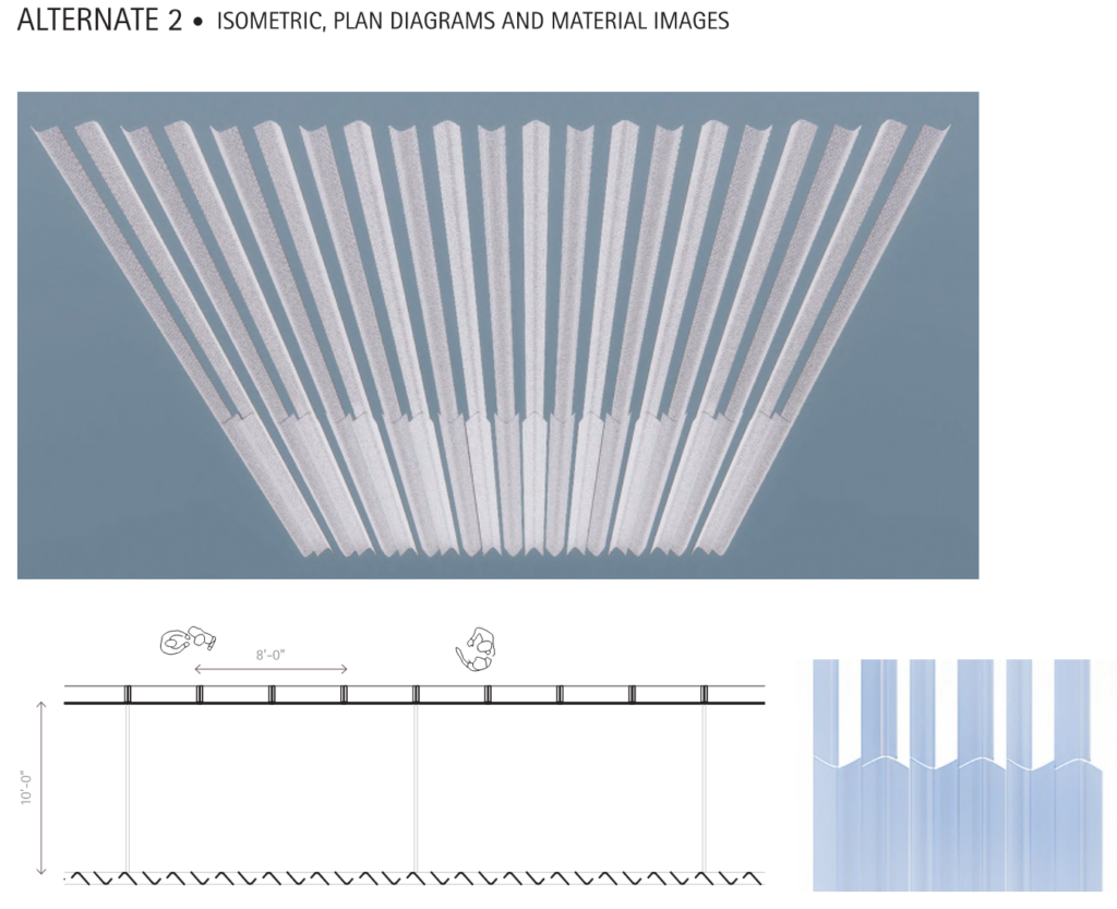
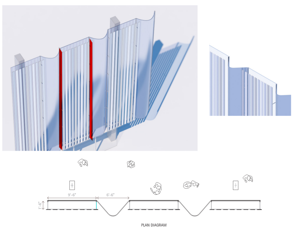
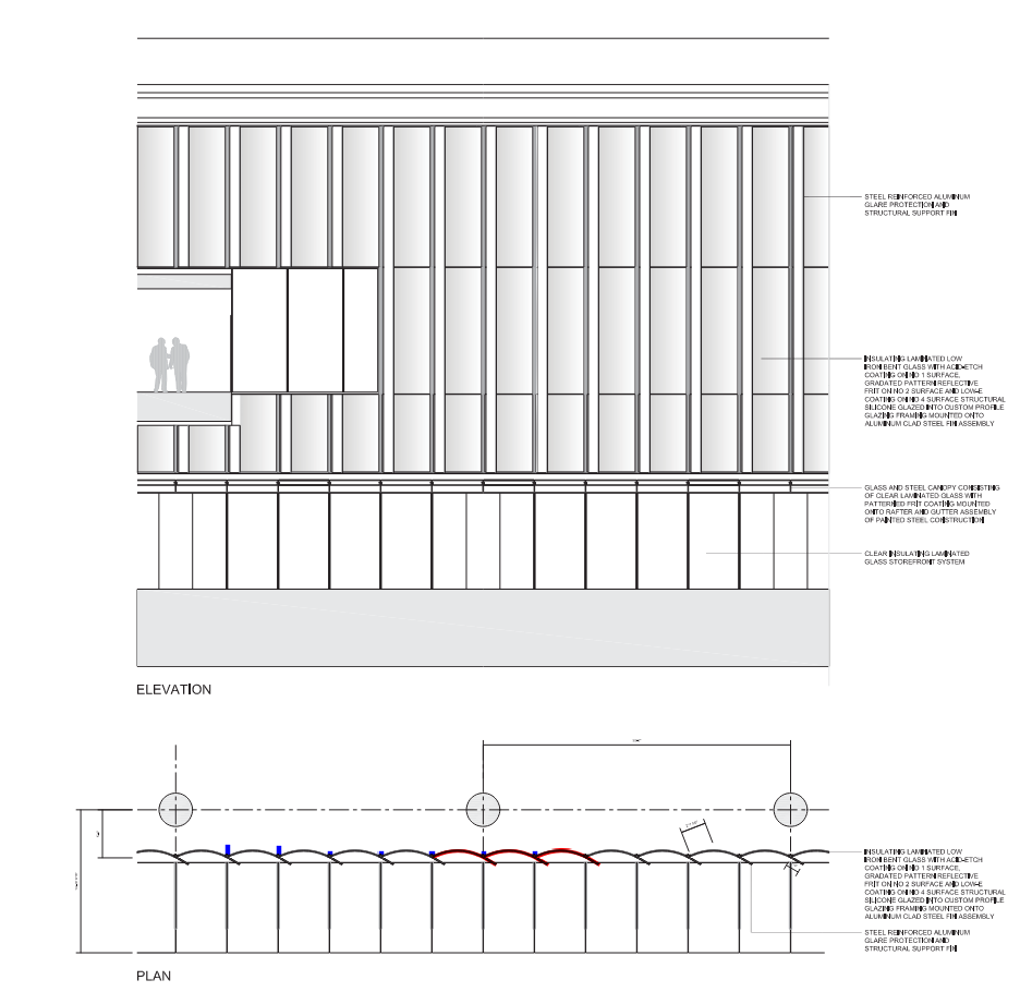
When Enclos was approached by Turner Construction in January of 2021, the design team for the project was in the process of evaluating multiple iterations of the bespoke facade for the headhouse. A major concern was daylighting and the potential glare for the staff working inside the ticketing area. Several strategies for creating shading and diffuse light were being explored. These included staggering the plane of glass from the front of the system to the back in alternate modules (figure 1), a floating curved and fritted glass brise-soleil 10’ in front of a flat glass facade (figure 2), and a staggered flat glass and curved glass approach with a floating terracotta brise-soleil in front of the flat elements (figure 3).
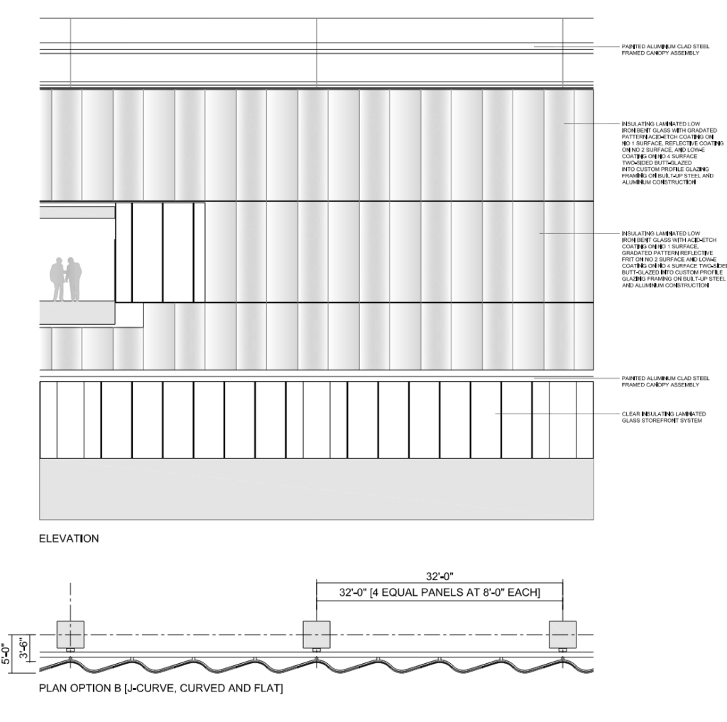
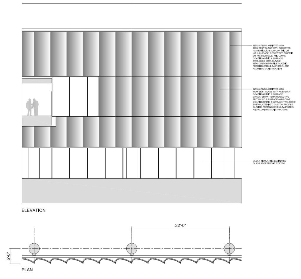
By the beginning of June 2021, the design had started progressing to a single facade skin, and the floating screen elements had been eliminated to reduce overall material costs and simplify shipping and field labor concerns. While slightly more traditional than the dual skin approaches, the three options being pursued were certainly not simple; Option A was a convex J-curved IGU on steel verticals (figure 4), option B was a concave J-curved IGU on steel verticals (figure 5), and option C was a flat glass facade with opaque glass fins of varying depths and heights spaced across the unit module (figure 6). In addition to the facade geometry itself, the load path for the facade was non-traditional as well. The prevailing thought was that the facade verticals would be hung from the canopy roof and braced back at the second-floor slab.
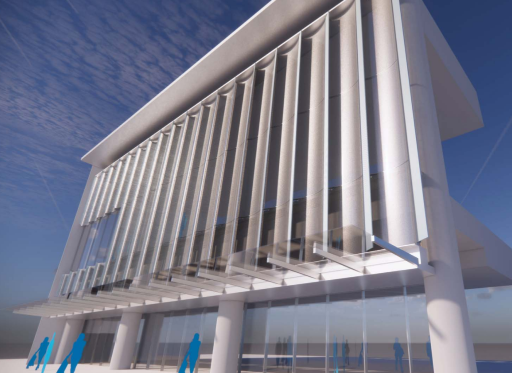
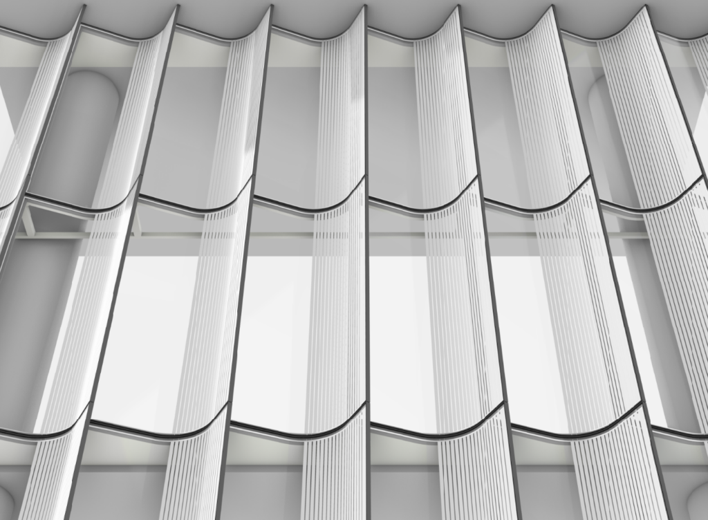
During all these studies, Enclos solicited vendor feedback as well as input from select manufacturing partners and our own field and shop crews to provide the design team costing models and budget pricing for the various iterations. By late June, the design had begun to coalesce around an option for a concave IGU glazed to a small aluminum cassette. The shop glazed cassettes were to be field hung onto the steel fin, which was the deadload support suspended from the roof as well as the shading device. At this point, the facade design also had a name – “The Luminous Wave Wall” and its expression was meant to evoke the interplay of light and water in the San Diego Pacific surf zone. (figures 10 and 11)
Exploring and Refining the Wave Wall
With the basic facade expression now relatively well defined, design studies began to turn towards optimizing the facade system for ease of fabrication and installation and furthering opportunities for material reduction. Enclos provided many details and renderings of iterations to the design team for their review and feedback. One early option was to put the steel verticals inside the weather line and to make the vertical fin aluminum (figure 8). Another exploration was to forgo the steel fin hung from the roof in favor of cantilevering the glass unit past the vertical to provide the shading. To do this would require supporting the cassette units from horizontal AESS steel trusses hung from the roof by rods (figures 9 and 10).
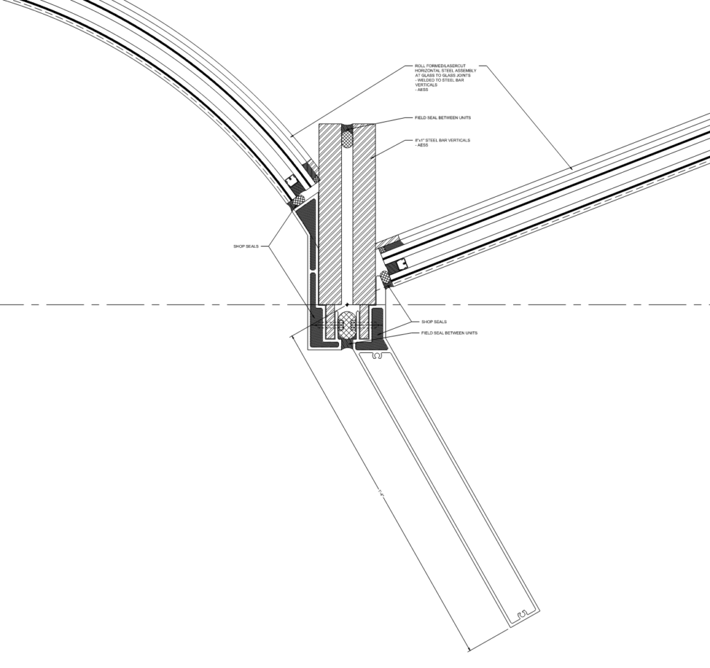
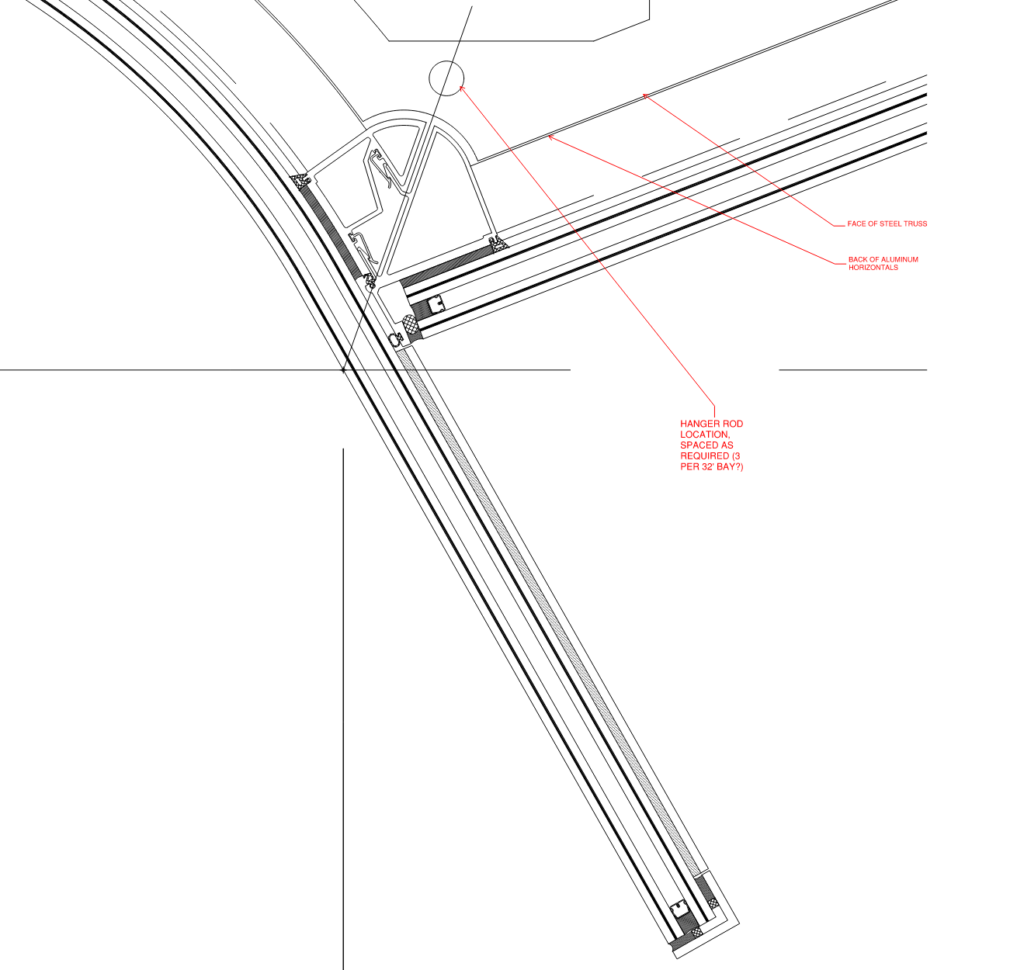
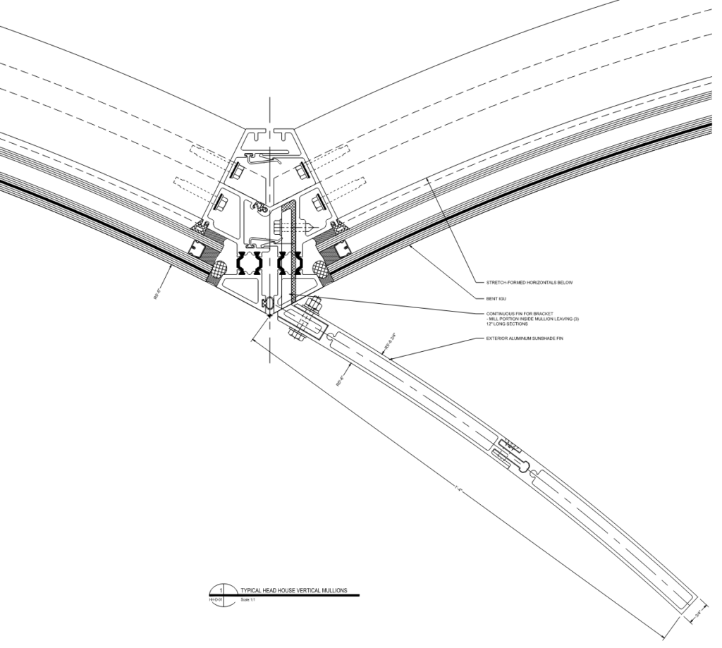
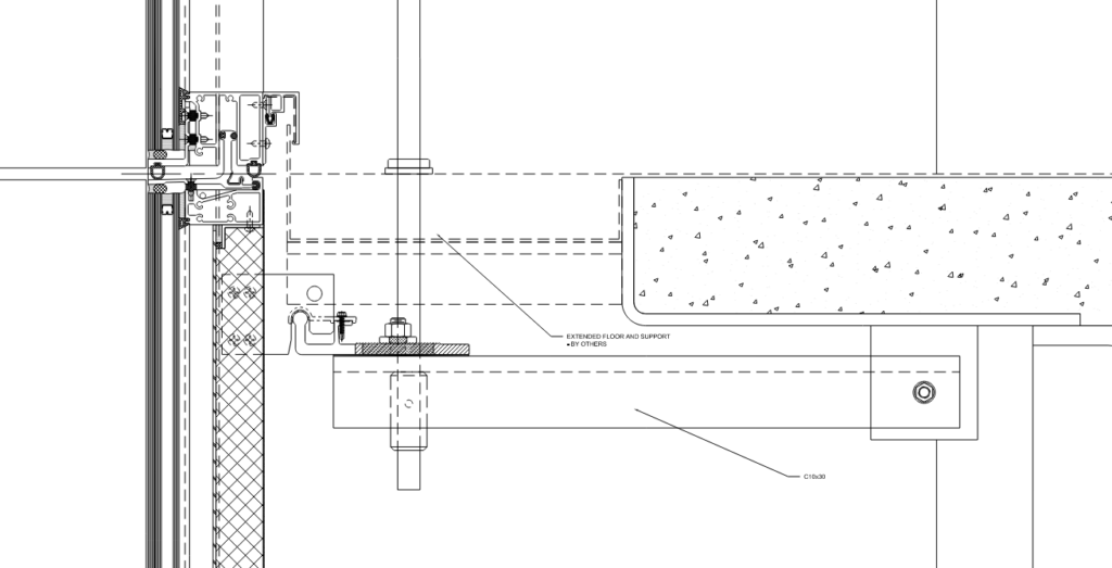
After pursuing the strategy of cantilevering the glass and its attendant fritting, it was determined that a metal fin was preferable for shading and logistical reasons. Due to the high cost of field labor for a stick or hybrid approach, the steel trusses for bracing the wall at the midspan of the double height space remained. This allowed for the complete unitization of the glass and a more traditional weather line for the facade, as opposed to steel verticals passing through the plane of the wall and bringing potential moisture and thermal problems (figure 11). The trusses would be hung from the roof, and the curtainwall units would be deadloaded to the roof. At level 2, the wall would be decoupled from the slab by a series of connections that would allow it to move vertically. Originally, this was conceived as being done with tension springs, but in the final detail, it was achieved with a hinged pin connection (figure 12).
Refining the expression
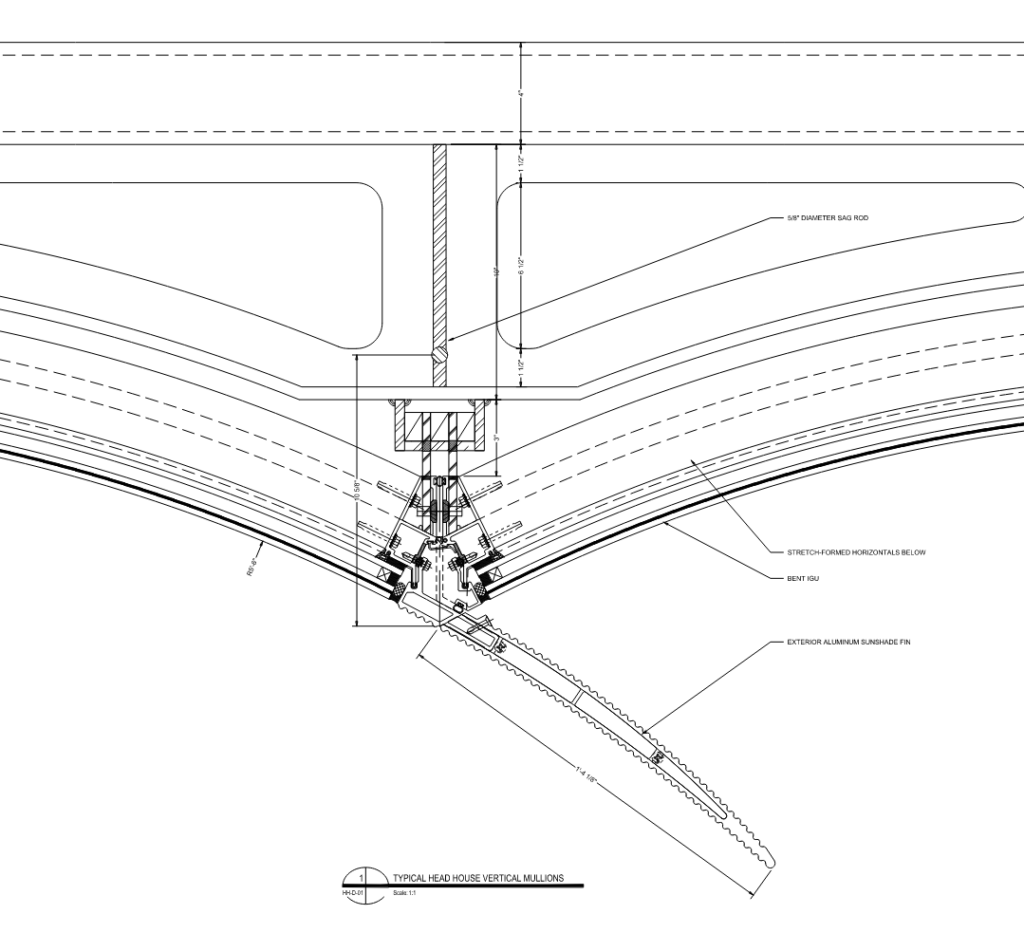
The typical glass lites for the headhouse wave wall are made with a half-inch thick laminated outer lite and a quarter-inch thick inner lite. They are concave curved with a constant radius of 5’-6” and a module spacing of 5’-4”. They were produced overseas by Beijing Northglass. Due to the heavy makeup and the complexities of getting curved samples in a timely manner, Enclos worked closely with the design team to refine the frit options using our visualization group to produce high-quality renderings for review. In addition to frit options, the design team used renderings to narrow in on sealant colors before producing a visual mockup.
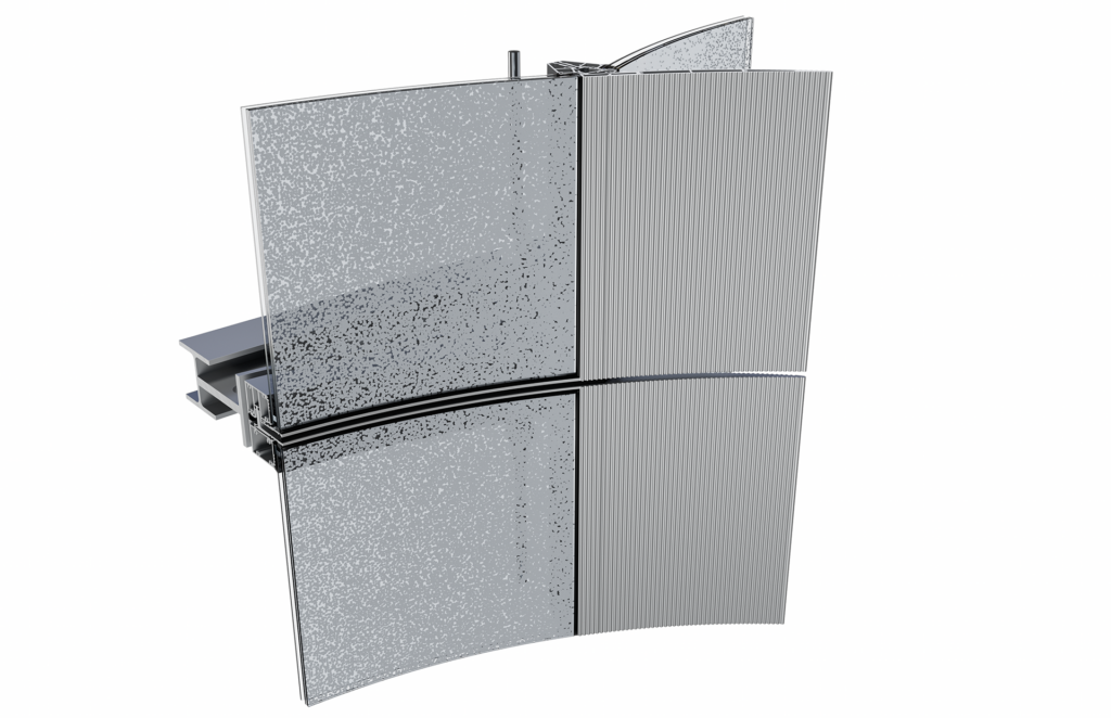
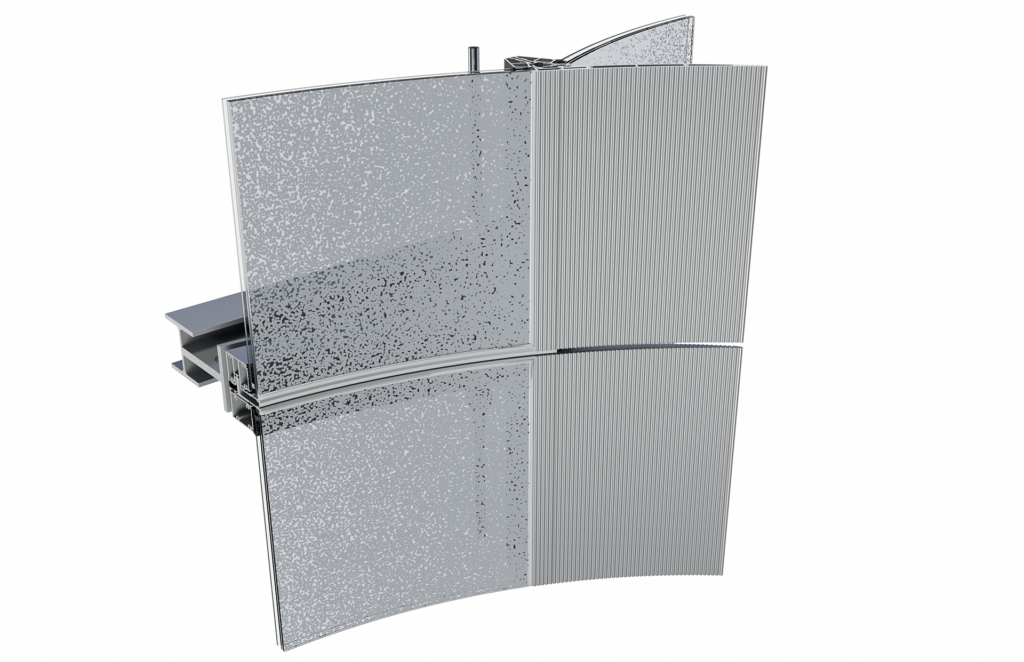
One of the early frit patterns the design team explored was a stochastic pattern of dots. A stochastic pattern is randomly determined with a probability distribution or pattern that may be analyzed statistically but not precisely predicted. This pattern designed by JCDA and Walter P. Moore gradated from transparent to opaque across the unit in width so that the shading grew increasingly dense as it approached the metal fin. Figures 13 and 14 show a four-way intersection with the stochastic pattern and two different sealant and gasket colors. In addition to refining the glass expression, the shading fin was given a textured treatment of vertical ridges in the die profile to carry the texture of the glazing infill into the shading device. (figure 15)
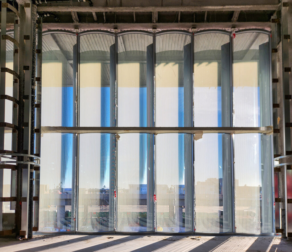
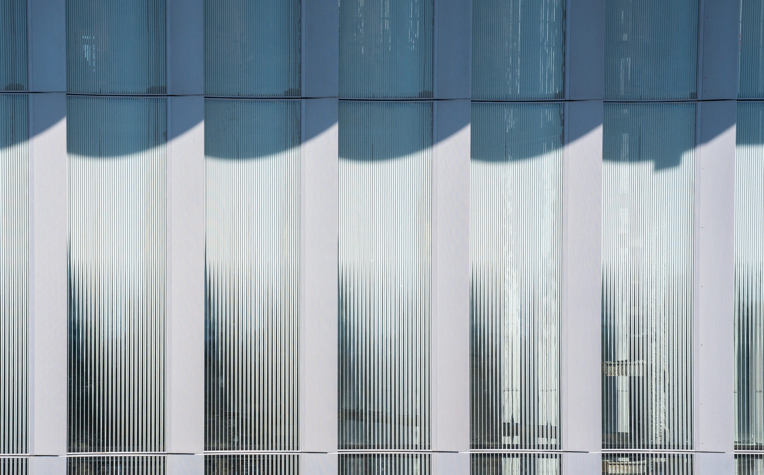
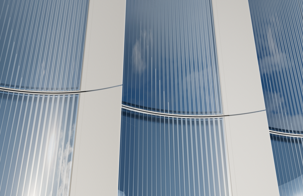
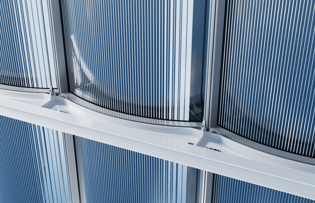
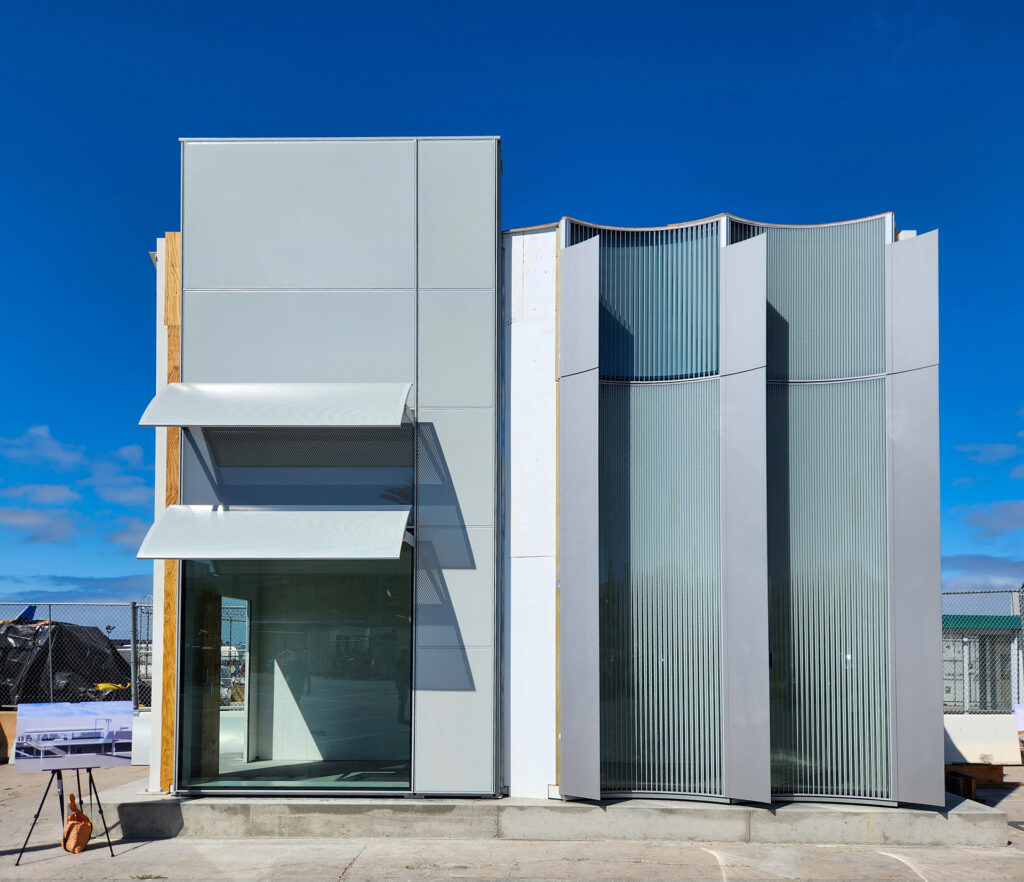
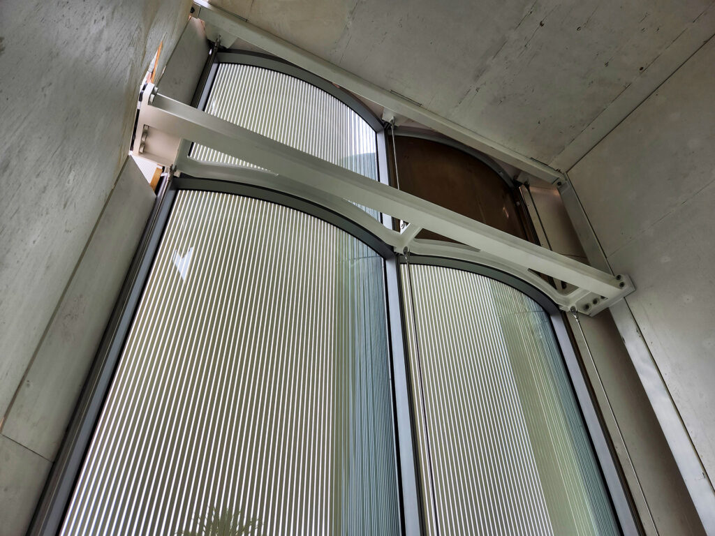
By the summer of 2022, the design team decided to forgo the stochastic frit pattern in favor of a gradated vertical pattern of lines that would change across the vertical height of the elevation. The gradated shading and fin explicitly address late afternoon sunlight at a low angle. The fin shades the portion of the glass, providing unobstructed views of downtown San Diego. Again, before receiving samples and building the physical VMU, the visualization group at Enclos provided the architectural design team with high-quality renderings as proof of concept. These were then developed through full-size mockups with JCDA. Figures 16 and 17 show the updated frit pattern renderings. Images 1 and 2 show the completed visual mockup. Note the two spandrel conditions are also being evaluated.
Ultimately, the success of the San Diego Terminal 1 Headhouse is due to the collaborative efforts of the entire project team. The innumerable decisions, both large and small, made during the design-assist phase as a collective group shape not just the expression of the facade and the quality of the componentry, but also impact the project schedule, the budget, and ultimately, the lives of the individuals tasked with building it and those who will experience being in it as workers or travelers. Enclos is proud to have assisted James Carpenter Design Associates, Gensler, Walter P. Moore, Starq, and the entire ARRIVE San Diego team in completing this modern infrastructure masterpiece.