By Austin Bensend, Director – Design Engineering, and Tom Peterson, System Design Manager
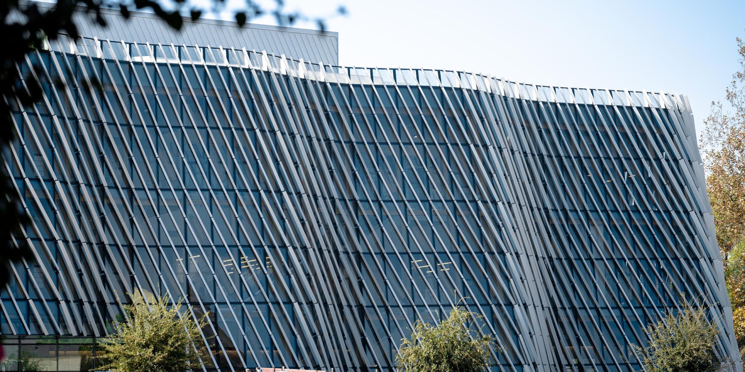
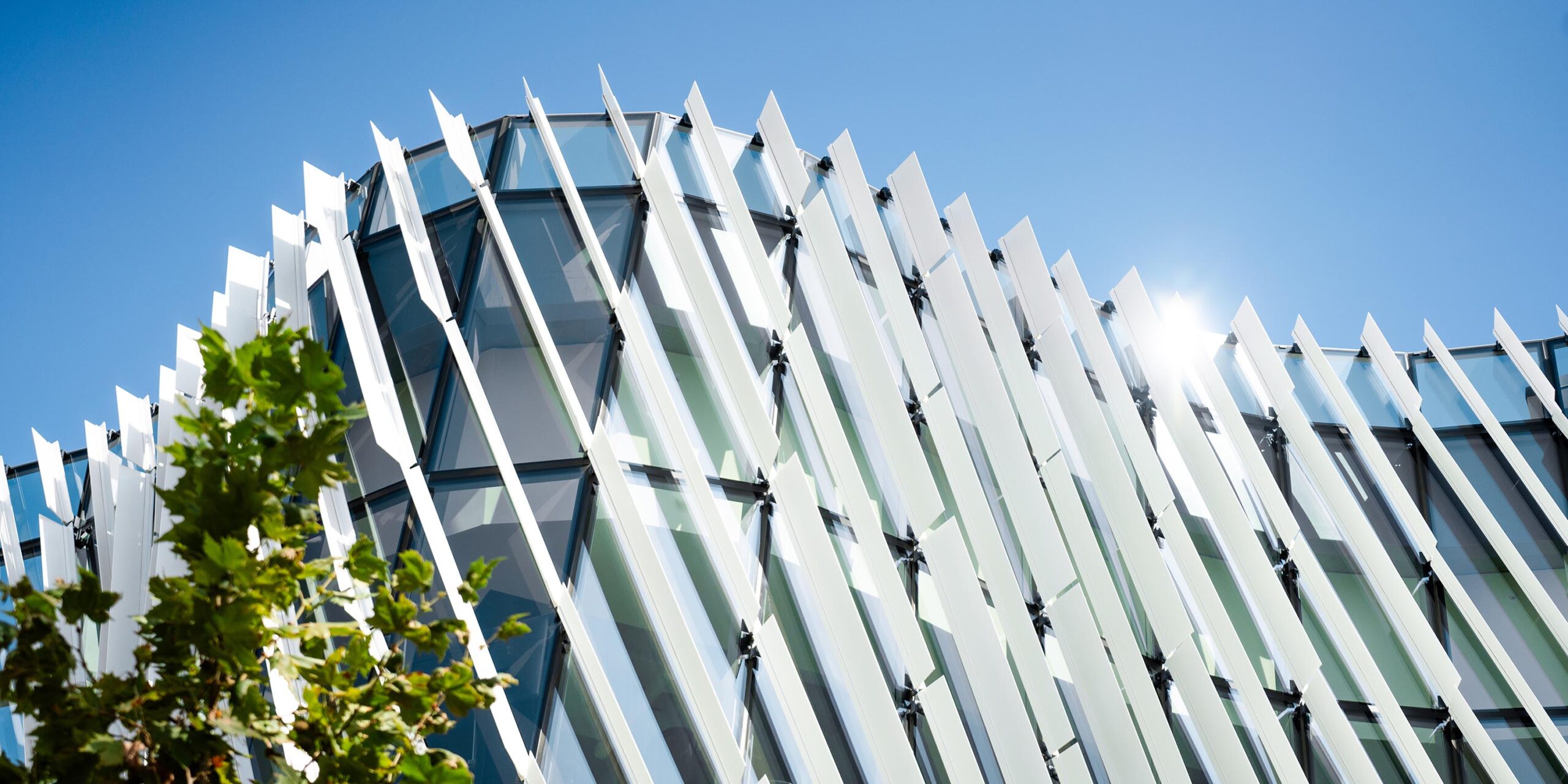
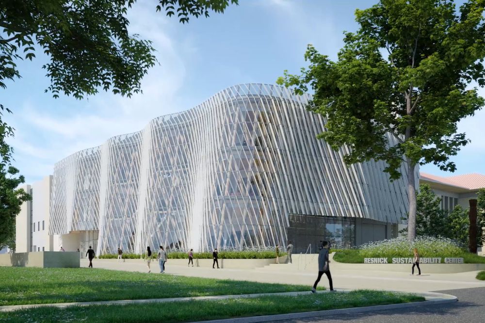
The Caltech Resnick Sustainability Center (RSC) redefines what’s possible in facade design, showcasing a breathtaking blend of glass and metal that flows with unexpected elegance. Conceived by the Yazdani Studio of Cannon Design, one of the most predominant displays of the RSC’s abstractive design is evident at first sight – its facade (Figure 1). In particular, the flowing geometry of the envelope is created from two materials that do not inherently or intuitively flow: glass and metal. The story of how such a facade was delivered has twin heroes: Cold Warping and Computational Design. Through many twists and turns, these heroes combined to deliver the bold vision for the RSC facade as a stunning example of what teamwork, artful ingenuity, and applied research can accomplish.
Designing for Efficiency
The initial concept for the building was a free-flowing, organic facade clad in diagonal features. The surface was initially detailed with triangular facets, which resolved the free-flowing nature of the facade into planar facets. However, from this faceted surface geometry it was observed that for every two triangular facets, an alternate facet element made of a warped quadrilateral could exist (Figure 2). Each module would consist of four linear, albeit non-co-planar edges in this scenario. From a surfacing standpoint, both triangular and quadrilateral facet approaches were deemed acceptable. As a result, a design study commenced comparing triangular facets in a traditional unitized-style curtainwall versus warped quadrilaterals in a hybrid, cassette-style curtainwall.

Traditional Unitized Curtainwall
Difficult Glazing & Increased Fabrication
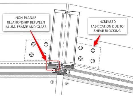
From the beginning, it was deemed essential that any unitized design could not involve mating vertical mullions together due to the wide range of bisector angles. The consequence was that the plane of the glass would not be parallel to the plane of the aluminum frame. The most significant impact of this decision was the difficulties in glazing the glass to the aluminum frame due to the non-planar relationship between the two materials. Another result of this design was increased fabrication due to shear blocking each corner of the aluminum frame (Figure 3).
Triangular Shaped Units
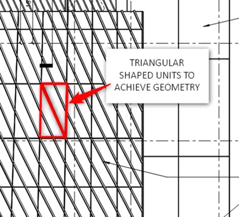
Selecting this design path would also result in triangular-shaped units, increasing installation costs due to the higher number of units to install and added material costs due to the 3-sided glass (Figure 4).
Decreased Thermal Performance
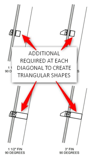
Choosing a 3-sided unitized approach would also impact thermal performance because of the added metal needed to create the triangular shapes (Figure 5).
Original Design Intent
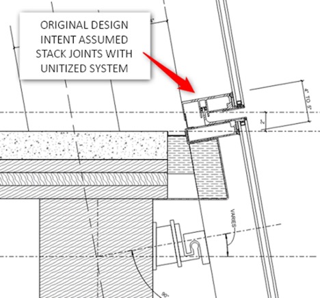
As shown in the bid documents, the original design intent called for a unitized approach, making it the expected method for the exterior facade contractor (Figure 6).
Cassette Unitized Curtainwall
Sustainability, Improved Thermal Performance, Reduced Material Cost
By combining the triangular-shaped units into bigger trapezoidal-shaped units, there would be a significant reduction in the required materials to construct the project. This approach would eliminate over 10,000 LF of diagonal aluminum framing, reduce glass waste by fabricating 4-sided glass as opposed to 3-sided glass, and remove the additional anchorage that would have been required at the diagonal timber members with the 3-sided unit design. Furthermore, by removing the diagonal framing, there would be an overall improvement to the thermal performance of the façade, therefore reducing energy costs. All of these advantages combined were considered to be a huge benefit to the project’s overall goal by being more sustainable and reducing overall material costs (Figure 7).

Versatility
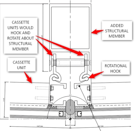
This design approach also proved useful in offering more versatility/flexibility by introducing an additional structural member that units would hook onto, thereby allowing the system to rotate about the additional structural member (Figure 8).
Cold Warped Glass
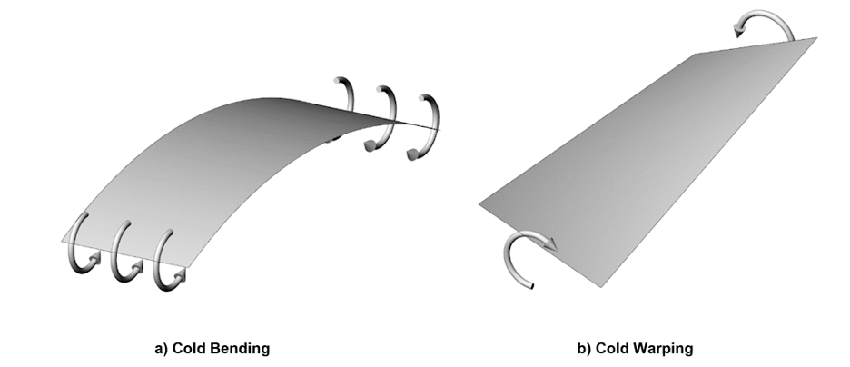
Lastly, and arguably the most critical consideration, the only way to achieve the quadrilateral approach would be to cold warp the cassette units to create the facade’s geometry. Cold-formed glass (including cold-bent, cold-warped glass) is a glass surfacing approach that involves taking a sheet of glass and forcing it into a geometry that differs from its original state through warping, bending, or a combination of the two (Figure 9). Cold forming is accomplished purely by applying external force and without using heat to deform the glass material. As a result, restraints are required to resist spring-back forces and maintain the geometry without the glass springing back to its initial shape. The glass is then held in the stressed state while in service.
Final Design – Cassette Unitized Curtainwall
Considering all the benefits of proceeding with the cassette-style cold-warped glass design, it was apparent that this would be the best approach for this unique facade. With the design path now established, the next steps were to determine how to achieve this unique cold-warped design in its final arrangement (Figure 10). The first step was finalizing the geometry, driven by the cold-warped glass engineering constraints. The second was finalizing the system components.
Step One – Finalize the Geometry & Glass Design
Surface Analysis
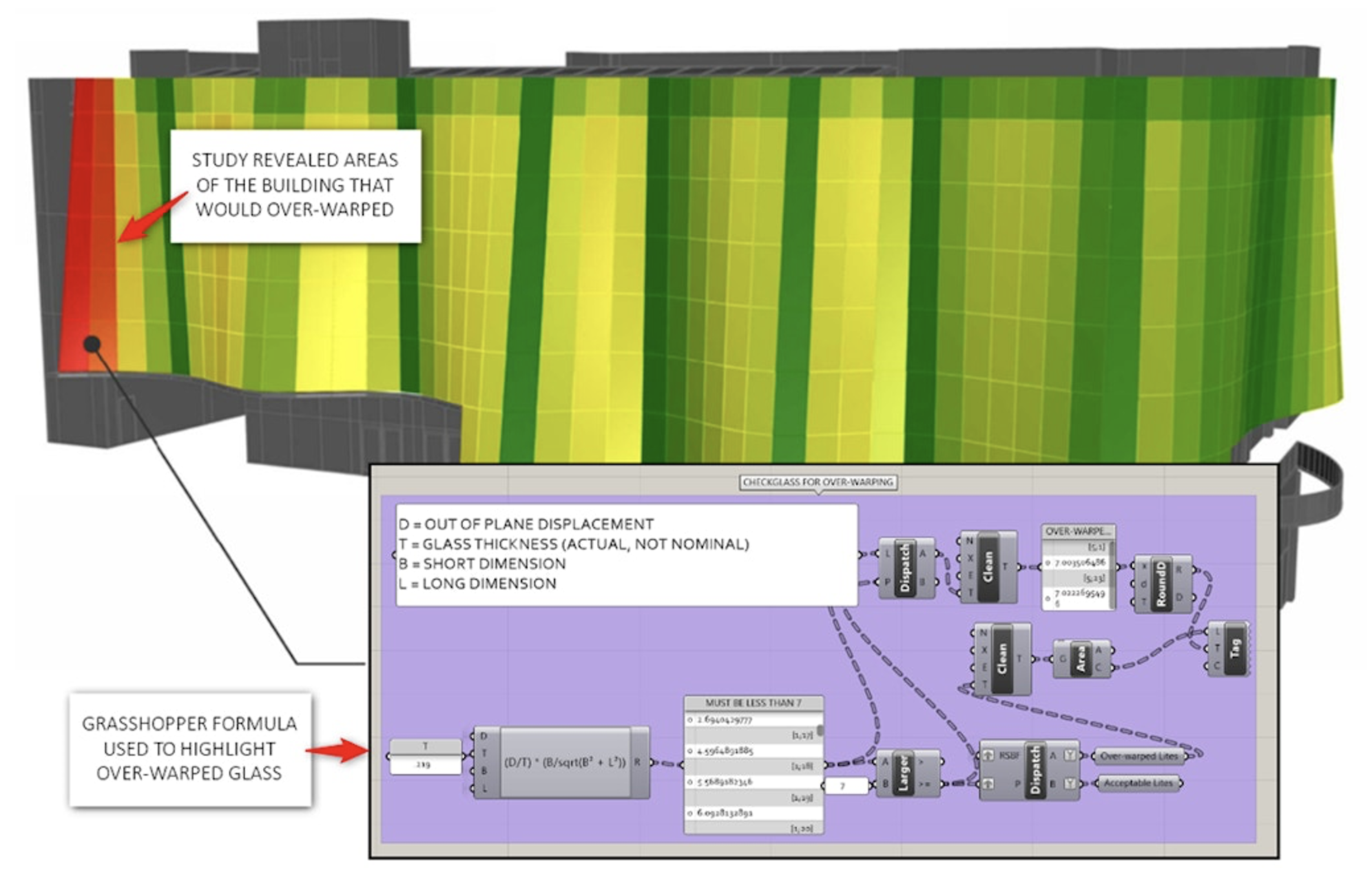
Starting with the architect’s geometry surface model, an analysis was conducted using a three-dimensional surface modeling software called Rhinoceros, coupled with a programming and analysis add-in called Grasshopper. An initial study revealed areas of the facade where the degree of surface curvature exceeded what was suitable for the cold-warping approach (Figure 11).
Finite Element Modeling
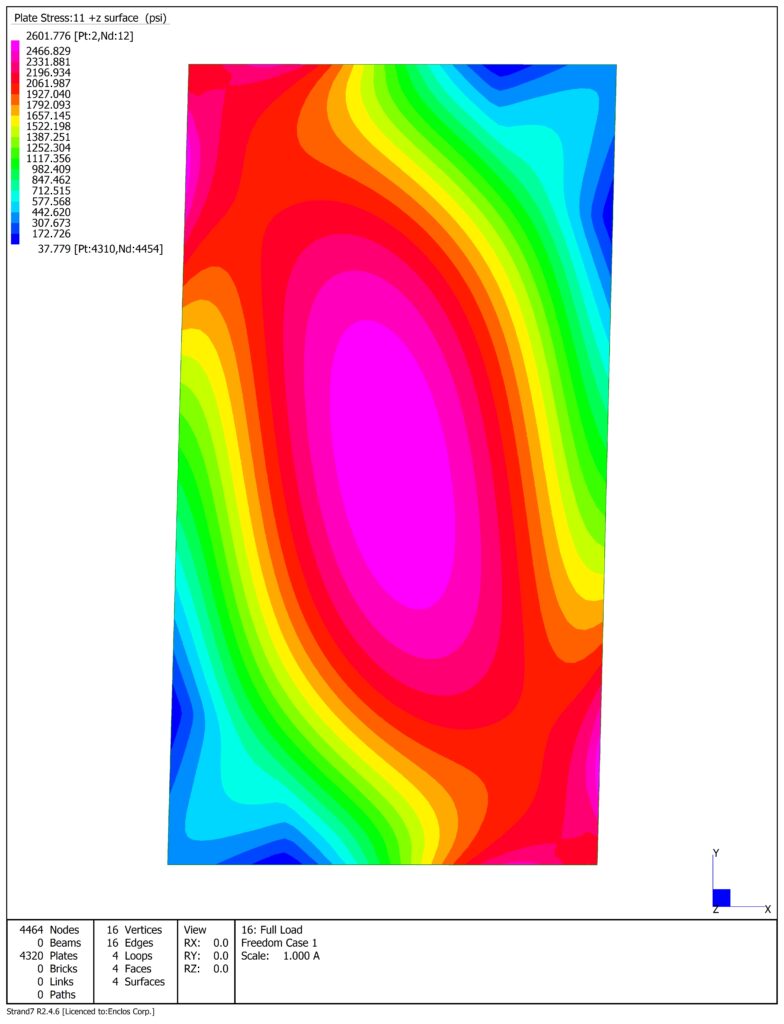
The surface analysis study was supported by the findings from previous research conducted by Enclos to validate finite element model predictions of the warped surface geometry. That research identified a ratio of twist, thickness, length, and width parameters for which the quality of the resulting warped surface would be preferable. Care was taken to keep the twist within this preferable range. The analysis was augmented with three-dimensional finite element structural modeling (Figure 12) to simulate the applied deformations and resulting glass stresses, residual spring-back forces, and surface quality of the glass. This analysis was also conducted to account for the modified stiffness of the glass due to warping stresses.
Glass Clamps
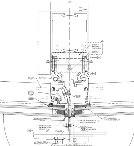
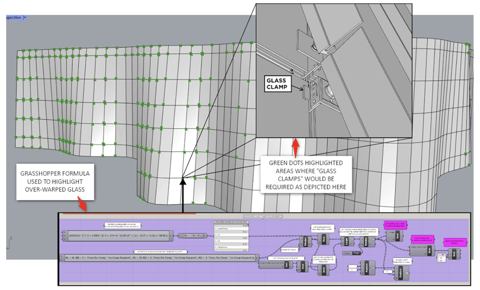
The study progressed with analyzing the long-term forces that the framing and structural silicone joints would be required to resist. From the outset, it was anticipated that some areas would require mechanical glass capture to achieve the degree of warping anticipated. Discussions with Dow, the structural silicone supplier, and the application of their research confirmed that mechanical restraints (glass clamps) would be included for specific areas of the project (Figure 13).
Frame Section Requirements
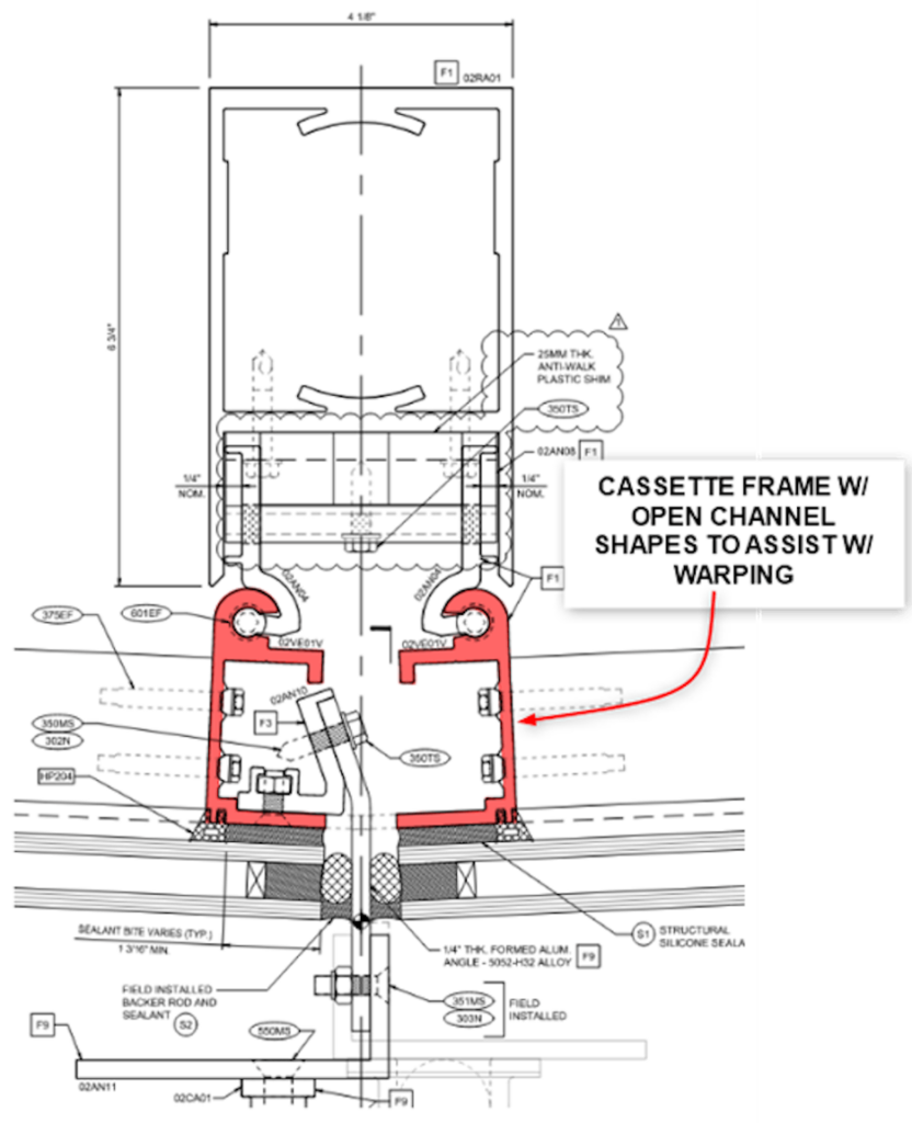
Given the warped surface, the frame would twist to achieve the desired geometry. Open shapes (not hollow profiles) were utilized due to their low torsional rigidity to minimize the forces that develop within the system during warping. The frame size was also minimized to aid with the strains on the structural silicone joint arising from warping. This resulted in a two-part framing approach: a primary “rafter” element that spans between floors and does not warp, and an individual “cassette” frame adhered to each glass unit that accommodates the warping (Figure 14).
Step Two – Develop the System
Rafters
Once the geometry and parameters were defined, the system components were next. The most critical component was the rafters, which provide primary structural support for the wall and determine its geometry. Multiple complexities would need to be considered to finalize the design.
Rotation at Splice Connections
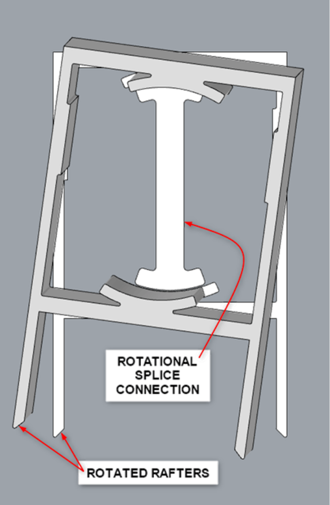
A splice connection was required in the rafters at each floor, and due to the twisting nature of the geometry, this caused the rafters to rotate from floor to floor, thereby requiring a rotational splice connection (Figure 15).
Unique Orientation to Surface Geometry
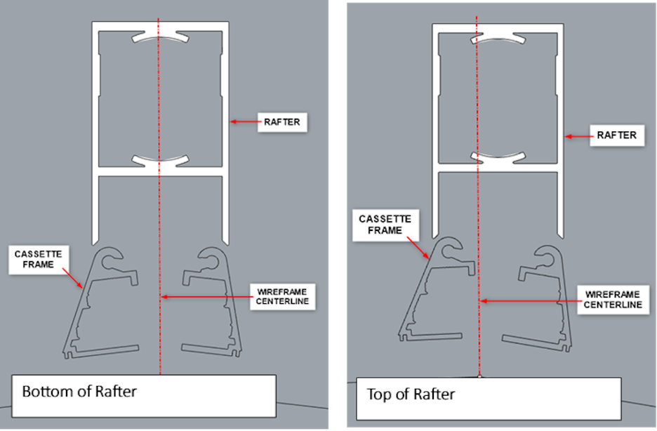
Because the rafters were not cold-warped, they did not uniformly follow the surface geometry. This resulted in an inconsistent relationship between the rafters and the cassette frame (Figure 16).
Connection to Structure
With the rafter and the structure sharing no common planes, each rafter required its own unique connection back to the structure.
Cassette Frame
With the position of the rafters now complete, the cassette frames could be fully developed. As with the other components within the facade, the cassette frame had unique challenges to decipher.
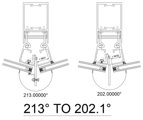
Angularity of Surface Geometry The bisecting angle between each cassette frame varied greatly. Grasshopper was used to evaluate the bisecting angle at each condition and group them into ranges to inform and help define the final shape of the cassette frame profiles (Figure 17).
Glass Silicone Bite
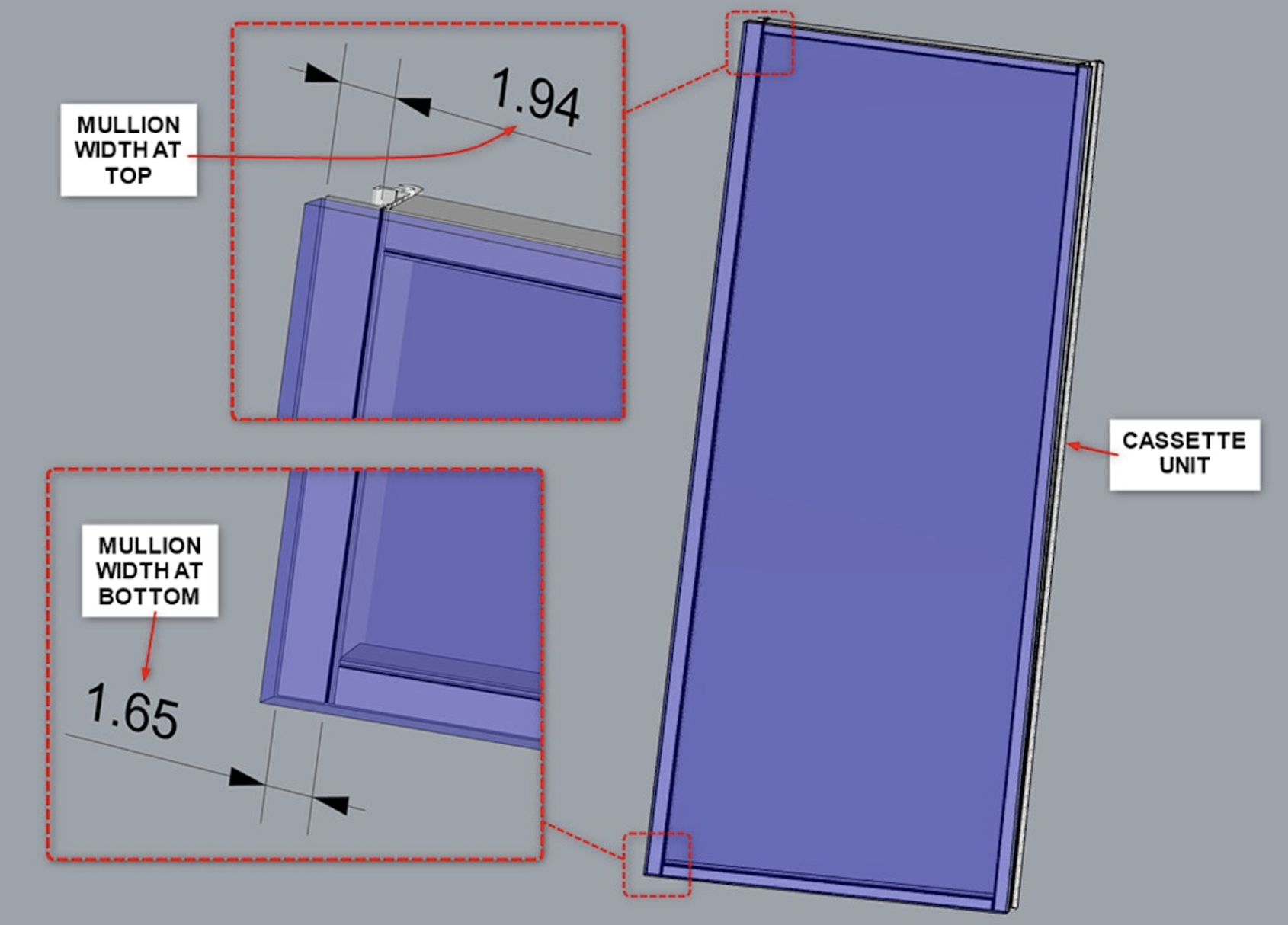
The relationship between the cassette frame and the glass needed to vary since the rafter-to-cassette frame relationship also varied. This would result in a fluctuation in the amount of silicone contact (Figure 18).
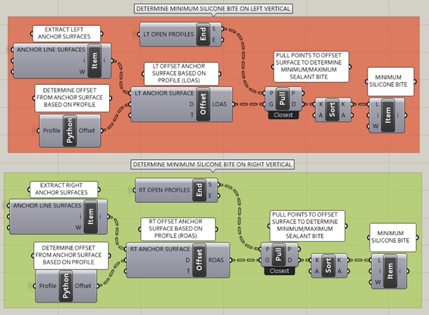
As previously discussed, the amount of silicone contact between the glass and the cassette frame was critical to the cold-warped design. Grasshopper was used to determine the amount of silicone contact at each glass lite’s top and bottom edge to ensure proper silicone contact was maintained (Figure 19).
Conclusion
Considering the final facade design for the RSC project (Figure 20), one can confidently conclude that the design path chosen was highly effective. Not only was it able to reduce waste and promote the sustainability effort of the project, but also able to deliver an effective and efficient design on a project where complexity exists in the most basic details. This project highlights how a cold-warped design approach combined with the power of computational design can be extremely effective. Computational design tools can provide abundant, valuable data that can be extracted from a model to help inform design. In the instance of the RSC project, these tools proved invaluable in developing the cold-warping parameters and aiding in numerous other design solutions. Intricate facade designs like the RSC project are rare, but with the right tools and knowledge, a design path that may seem bent and twisted can transform into a straight and linear path.
