By Dan Bettenhausen, Director of Mechanical Engineering & Adam Krueger, Mechanical Engineer
Energy codes and environmental policy continuously evolve to harness advances in glazing technology. In recent years, a movement has emerged from within the construction community to understand and reduce the impact of commercial buildings on energy use and carbon emissions. It has become increasingly common to consider the “embodied carbon” associated with the formation, processing, and handling of materials as well as the “operational carbon” that stems from the use of products created from those materials. Glazing products are commonly viewed through both lenses. Analysis of embodied carbon is a seemingly straightforward process that examines the lifecycle of a given product and is largely dependent upon the energy sources consumed during each stage of material procurement, manufacturing, installation, use, and potential recycling. A need has been identified for commercial glass products that can be recycled since glass production is an energy-intensive process. Operational carbon associated with glazing is less often analyzed due to the inherent complexity of buildings and abstraction that must be overcome to trace utility use to individual building components. This article is the first in a multi-part series to address the historical development progress toward producing market-viable glazing products that enhance commercial buildings’ energy efficiency and sustainability. Herein, we will explore the history of conventional glazing products and connect their inherent performance with scientific principles.
History of Insulated Glazing
The use of air cavities to enhance the insulating properties of fenestration dates back many centuries to the first use of shutters, which offer greater protection from harsh weather than a single panel of glass can provide. The first crude multi-layer glass products are thought to have emerged in Europe in the late 1800s. In many cases, these installations consisted of adding a layer of glass to existing windows with adhesive putty.
In 1865, American engineer and inventor Thomas D. Stetson filed a patent for an insulated glass unit (IGU)1. His design showed two glass panes bound together and hermetically sealed to make a single unit with dehydrated air. A timber spacer bar was adhered to separate the two panes of glass with an adhesive putty. Unfortunately, Stetson’s patent did not see mass production during his lifetime due to a lack of capable production plants and funding.
It was not until the 1930s when Charles D. Haven, a refrigeration engineer, and John Hopfield, a physicist, commercialized the technology under the name “Thermopane”22. This product evolved from testing double-paned glass enclosures to replace conventional storm sashes. Since storm sashes utilize an unsealed air cavity to achieve insulation, they are prone to being fouled by condensation. Haven’s invention mitigated the risk of condensation by sealing the cavity with laminated rubber strips between the glass lites bonded by a mixture of alcohol and shellac and coated with a liquid seal. The cavity created was purged of humid air entrapped during assembly using a system of hypodermic needles.
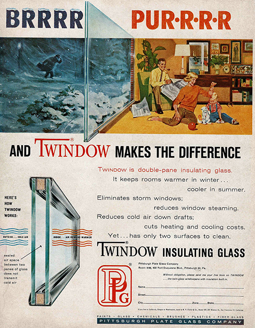
Thermopane and similar products, similar to those still used today, became commercially available in the 1950s and gradually gained adoption. Rising energy costs throughout the 1970s contributed to the eventual obsolescence of single-lite glass and fueled additional innovations to improve the ability of products to insulate buildings from solar and temperature-driven modes of heat transfer. Solar control strategies had evolved by this point, employing colorants embedded within the float glass and mirrored coatings, which became ubiquitous in many commercial buildings’ “all glass” appearance in the 1970s.
These advancements were not without flaws. Heat absorption increased stress in the outboard lite, often requiring heat-treated substrates and the attentive risk failure due to nickel sulfide inclusions. The propensity of mirrored finishes to amplify flaws, such as roller wave distortions, imparted by heat-treating processes was found to be objectionable by many architects. Throughout the 1990s, increasingly transparent soft-coat “Low-E” products achieved greater appeal and are still popular today.
Anatomy of Modern Insulated Glazing Units (IGUs)
Today, insulated glazing units have come a long way from Stetson’s early patent and incorporate a variety of energy-conserving features according to the needs of a given application, including:
Conventional Products
- Colored substrates, interlayers, films, and coatings
- Frit patterns, digital printing & opacification
- Low-E and Reflective Coatings
- Low Conductance Edge Spacers
- Inert Gas Fills
Commercialized technologies trending toward broader implementation
- Triple Glazing
- Electrochromic and Thermochromic Dynamic Glazing Layers
- Photovoltaic Glazing
Emerging innovations that are in the early stages of commercialization
- Vacuum Insulated Glass
- Slim Triple Glazing with Ultra-Thin Glass
Insulating glass units today retain the same configuration of fundamental components imagined by Stetson in 1865; however, technological advances have resulted in IGUs that are more energy efficient, higher quality, and available in a much broader array of appearances to suit a project’s specific architectural requirements. In fact, a level of sophistication has been achieved that allows for variation of opacity to suit dynamic solar conditions either by an electrochemical process or in accordance with the intensity of incident radiation. The construction of a modern insulating glass unit is depicted in Figure 1, which illustrates two panes of glass separated by a hermetic air space sealed at its edges with a “dual seal” spacer assembly. The edge spacer, commonly consisting of a desiccant-filled metallic sleeve perforated at its internal boundaries, features a primary butyl seal to form a vapor barrier between the glass panes and a secondary structural seal inboard of the assembly for resilience.
Heat Transfer
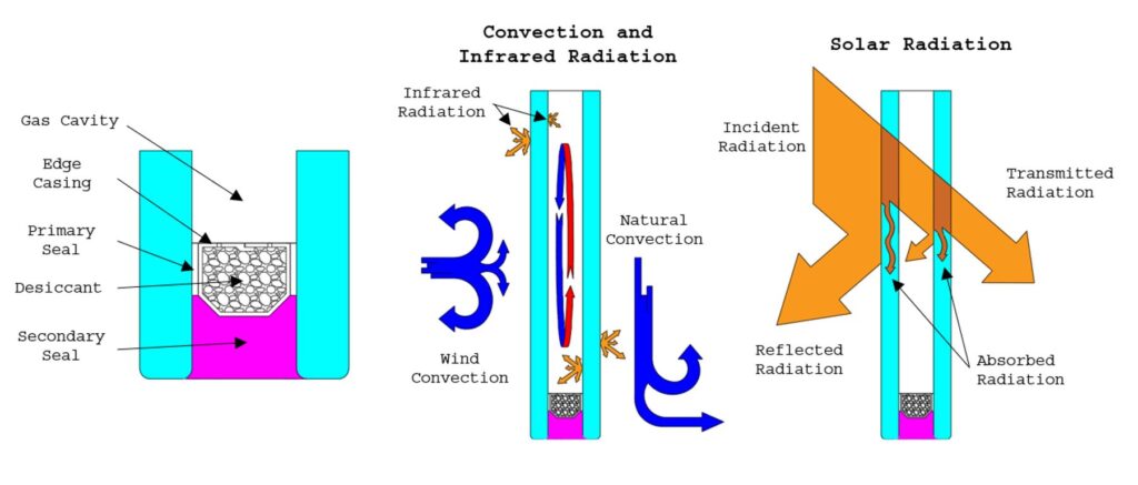
Energy consumption by space conditioning equipment is influenced strongly by glazing when it represents the sole weather barrier that separates the controlled interior environment from variable exterior conditions. Analysis of the net rate of energy transfer across the envelope is complicated because the potential for heat flow is motivated by different sources. For instance, on a sunny winter day incident solar energy may act to drive heat transfer into the occupied space while the temperature difference from interior to exterior directs heat transfer in the opposite direction. The propensity of materials to absorb solar radiation may affect this balance; however, this complexity is generally disregarded by standards and codes. It is more common to differentiate heat transfer that occurs due to “local temperatures” and solar radiation with separate representative metrics of U-factor and Solar Gain, which are calculated using independent sets of environmental conditions. The U-factor is the coefficient of conductance, which establishes the proportionality of the heat transfer rate through the glazing to its area and the interior-exterior temperature difference. Solar gain is commonly expressed as a solar heat gain coefficient, the portion of incident solar radiation transmitted through the glazing.
As designers, it is relevant to our interests to understand how the specifications of a given glass makeup affect heat transfer through that assembly. We can gain some intuition by tracing the heat transfer path through each material layer. It is worthwhile to pay credence to the influence of the interior and exterior conditions. While they are not a material specification, they influence heat transfer. Externally, incident solar radiation is affected by numerous factors such as geographic location, the surrounding environment, sky cover, and time. The exterior temperature and how wind influences convection are important. Interior conditions are often affected locally by the function of perimeter space conditioning equipment, obstructions that might be placed near a wall system, and interior temperature. When observing metrics such as U-factor and SHGC, it is intelligent to consider if the environmental conditions specified by a given standard are consistent with those of the actual use condition.
The thickness of the glazing is generally not a very significant design consideration when evaluating an insulated glazing unit. Unless the glass is colored, it is unlikely to be very heat absorbing, and solar control coatings have all but replaced the use of colored glass as a solar control mechanism. For most conventionally sized insulated glazing units, it is also true that the thermal resistance of the gas cavity is far greater than that of the glass itself.
Subsequently, the energy performance of an insulated glazing unit is most greatly affected by the attributes of its insulating cavity and any solar control coatings that are applied to its surfaces. In the absence of solar radiation, heat transfer is strongly affected by the width of the glazing cavity. It is by no coincidence that the width of gas cavities commonly ranges from 3/8” to 5/8.” For thicknesses below 3/8”, gasses are nearly quiescent with very little convective movement, and thermal resistance increases attentively with increasing cavity width. For thicknesses exceeding 1/2”, convective air movements become appreciable and begin to increase heat transfer. In fact, for very large cavities exceeding those of commercially available products, the effect of convection on heat transfer can become quite complicated.
Radiation between the inward-facing surfaces of the gas cavity achieves the same order of magnitude as those corresponding to convection if the glass is uncoated; however, the presence of reflective “Low-E” coatings that are typically applied to the second surface greatly reduce the net rate of radiation heat transfer. The term “Low-E” denotes “low emittance.” It is a tenant of heat transfer that, at a given frequency of radiation, the propensity for a body to emit thermal radiation, as a function of its temperature, is directly related to its propensity to reflect radiation. Thus, a reflective coating is also “Low-E.”
Glass Treatments to Control Solar Gain
Colored Glass
Tinted glass can exhibit a modest amount of solar control since the opaque solids that color the glass absorb incident solar radiation in the outboard lite. The color chosen and degree of opacity strongly influence whether a significant effect is achieved. Since color selection is an esthetic consideration, thermal performance benefits are generally a secondary consequence of architectural intent. In some cases, neutral colors such as gray, green, or bronze are used in tandem with solar control coatings to achieve an enhanced effect while also controlling glare. These advantages must be weighed against reductions in daylight and the potential for increased thermal stress. It is noteworthy that float glass, by nature of impurities inherent to the manufacturing process, exhibits a pale green hue. The architectural desire to create an expression of communication with exterior spaces has yielded a demand for “ultra clear” substrates that diminish these impurities to enhance the transparency of the glass. While this effect is generally perceived to be beneficial, it is noteworthy that solar gain through the glass itself can increase as much as 10%.
Reflective Coatings
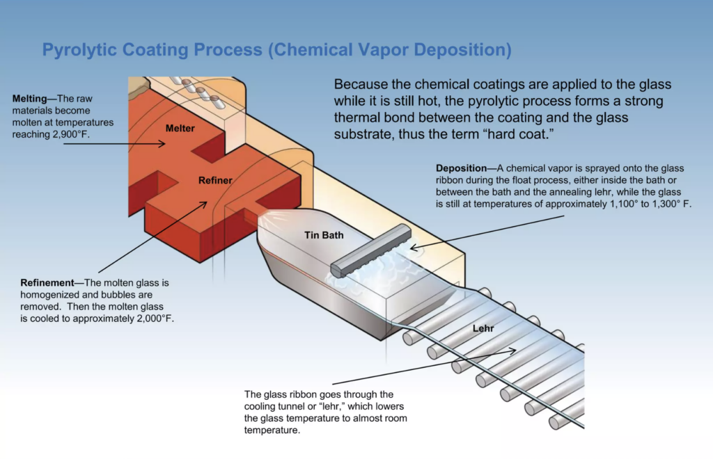
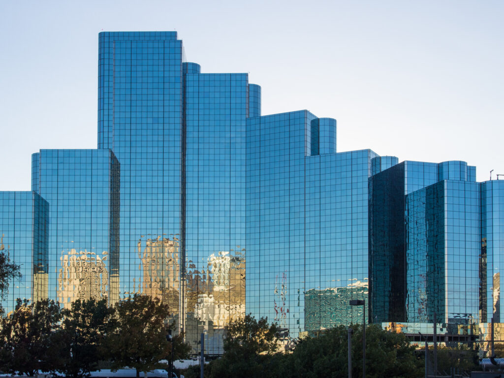
The high inherent costs of glass tinting motivated the exploration of coating technologies and adaptation of existing technologies, such as chemical reduction processes already employed for producing silver mirrors. During the early 1960s, commercial products such as Glaverbel’s “StopRay” products became available, which initially employed gold as a base metal. Throughout the 60s and early 70s, PPG’s early “Solarban” products expanded this process to include Silver, Copper, Cobalt, and Nickel3. Coatings produced by these processes were very dark, with less than 20% light transmittance. Subsequent advances incorporated processes that applied coatings directly to the hot glass float, either by spray application or chemical vapor deposition, employing metallic salts, as depicted in Figure 2. Highly reflective glass gained subsequent popularity during the second half of the 20th century, particularly for large multi-story buildings since the apparent inward opacity was convenient to disguise spandrel areas at floor slabs, rendering an “all glass” look from the exterior. While the outward appearance of reflective glass was often dark, glare and solar control were greatly enhanced relative to clear or tinted glass.
Low-E Soft Coats
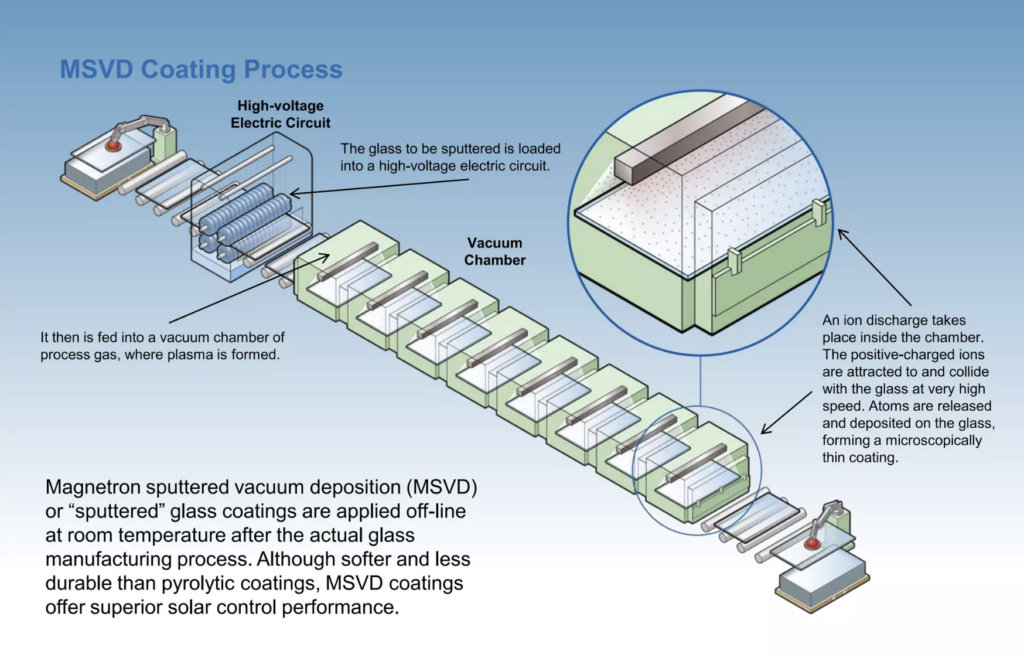
During the 1980s, significant advances were achieved in “sputter coating” glass, whereby ionized gas particles are accelerated toward a source of coating material in a vacuum chamber by the influence of a strong magnetic field and cathode. This process is called Magnetron Sputtering Vapor Deposition (MSVD). Particles are released from the metallic source, commonly silver, with high energy by the bombardment of gas ions, creating a plasma that adheres a fine metallic layer to the cooler glazing surface as it dwells in the sputter chamber. Optimization of such processes did not occur without trial and tribulation. An early attempt to commercialize the technology in the 1960s by Glaverbel failed when it was discovered that scaling up the process equipment resulted in non-uniformities3. After various iterations throughout the 80’s and early 90’s, modern in-line magnetron sputtering became common.
Unlike pyrolytic coatings, sputtered “soft coats” are vulnerable to damage and must be placed within the IG cavity, typically on the inboard face of the exterior lite. Furthermore, sputter deposition requires a batch process since glass needs to be pre-cut to accommodate the staged vacuum chambers used. These limitations are upended by modestly better energy performance and greater control of certain esthetic parameters. Notably, pyrolytic “passive” coatings, tuned to transmit solar energy while still rejecting glare, may be advantageous in certain heating climates where increased solar gain is desirable. Advances in both technologies have yielded increasingly neutral appearances that are only subtly different than clear glass, so it is no longer appropriate to suggest that choosing either application would yield a higher quality or better-performing product. The highly reflective coatings that were once a prominent feature in urban landscapes have since ceded a wide range of tints and reflectance that coincide naturally with desired esthetics while reducing operational energy use.
Room Side Low-E
It seems fitting that the quest to improve energy efficiency further would establish a harmony between “hard coat” and “soft coat” processing technologies. Modern coatings’ transparency allows both to be used in tandem without significantly sacrificing light transmittance or resulting in unacceptable esthetics. For example, a double-lite insulated glazing unit with a soft coat Low-E on the second surface and a durable hard coat on the interior exposed surface can exhibit excellent solar control and a better U-factor than conventional Low-E since a significant portion of interior radiation is reflected into the space. As a cautionary note, it’s important to recognize that even though net heat transfer is reduced, this application does lower the temperature of the interior surface of the glazing, which could pose problems in high-humidity environments.
Fritted Glass
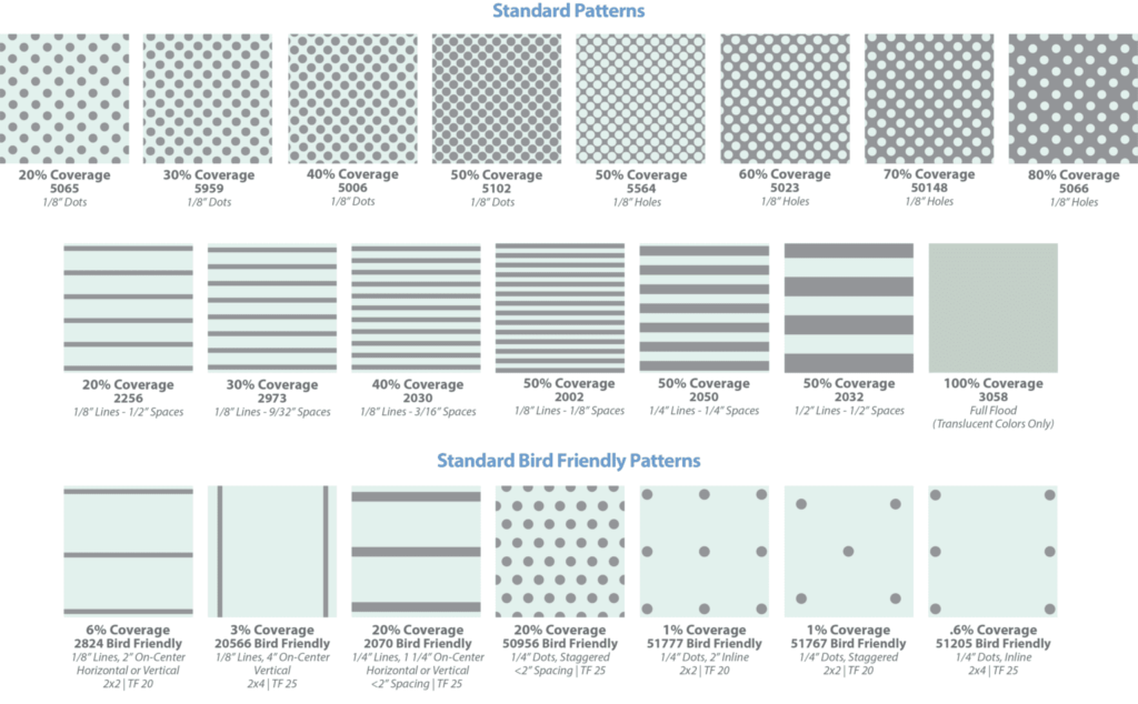
Frit, embellishing surfaces with ceramic paints fired in an oven to produce a “baked on” hardened coating, cannot be regarded as a recent innovation. Its invention predates the use of glass in windows. Early products of this process are observable in ancient artifacts such as tomb paintings in Egypt and jewelry in Mesopotamia5. Modern frit coatings applied to architectural glazing employ a similar process aided by modern manufacturing technology. Paints are conventionally applied using a silk screen process whereby the glass is masked with a perforated design and coated. Residual paint is removed with a squeegee before the screen is lifted, imparting the desired pattern. The recent innovation of “digital printing,” which resembles ink jet printing, can also apply frit ink and is invoked when elaborate images and variations of color are specified. The painted glass substrates are then heated in an oven to fuse the paint to the glass. Fritted glass is commonly used as an aesthetically desirable form of solar control since the artistic patterns also filter solar radiation by absorbing it in the outboard lite. Another utility of frit is that it can be used to create “bird-safe” products, which reduce the risk of avian collisions. It is noteworthy that recent research studies, such as those initiated by Dr. Scott Norville during his tenure at Texas Tech University, have correlated a reduction in the compressive strength of heat-treated lites with the application of frit, which may require tempering of the glass to achieve adequate resistance to thermal shock in certain applications6. An assortment of common patterns is shown in Figure 4.

Edge Spacers
The edge spacer assembly applied along the perimeter of an insulated glazing unit performs three important tasks. The structural element attaches individual glass lites to form an assembly, hermetically seals the glazing cavity, and houses the desiccant required to absorb moisture entrapped within that space during manufacturing. Insulating glazing units are assembled with different kinds of edge spacers in accordance with performance requirements. Factors affecting selection include necessary condensation resistance stemming from the occupancy type of the building and local climate, desired U-factors, esthetics, and cost. Edge spacers are conventionally categorized in terms of the material used for the spacer casing, which can be either aluminum alloy, stainless steel, or composite polymer. In these cases, the casing is perforated where it bounds the IG cavity and is filled with a desiccant material, as shown schematically in Figure 1. Edge assemblies that employ a casing commonly employ a “dual seal,” where the casing is sealed against the glass with a butyl sealant to mitigate water vapor transmission and a secondary structural seal that is not necessarily impermeable to water vapor bond the glass. Some recently innovated products do away with this configuration by replacing the casing with a foam material formulated as a desiccant. In this scenario, adhesive foil is used to complete the vapor barrier. The material’s thermal conductivity has the greatest influence on the level of performance achieved. Aluminum products exhibit the highest thermal conductivity, contributing to increased heat transfer at the “edge of glass” and colder glass edge temperatures in heating environments. The alternate materials described are referred to as “warm edge” since they produce elevated edge temperatures, reducing the likelihood of condensation. The thermal conductivity of stainless steel is approximately a tenth of the value corresponding to aluminum. The use of polymer or foam is sometimes distinguished as “true warm edge” since the lexicon of the term “warm edge” was first associated with stainless steel products. The thermal conductivity of those materials is yet another order of magnitude smaller than that of stainless steel. Metallic spacers are commonly offered as either mill-finished or black. Polymer and foam products are typically black or sometimes gray. It’s noteworthy that edge spacer widths are available in standard sizes, and it is commonly necessary to consult with manufacturers to determine the availability of specific products for unique glazing configurations.
Gas Fill
As described, insulating glass units achieve greater thermal resistance than a single pane of glass by virtue of the cavity formed between the glass layers. For many years, air-sealed within this space because of the manufacturing process was the only “gas fill” that was commercially available. Recall that the thermal resistance achieved by the gas layer is aided by the low inherent thermal conductivity of the gas but is detracted from by convective air movements, which act to mix the fluid. Consequently, convection is strongly influenced by the viscosity, or “stickiness” of the gas. While it is perhaps not intuitive to regard gasses as being sticky, they exhibit this quality to a fine degree. The action of buoyancy, which causes “warm air to rise and cold air to fall,” is resisted by the cohesive action of viscosity. The desire to achieve greater thermal performance motivated the exploration of alternative gas fills that could further reduce heat transfer. Certain noble gasses were thought to be good candidates because they are stable, do not participate significantly in thermal radiation, have lower conductivity than air, and have comparable or greater viscosity. Of those, Argon is the most commercially viable due to availability and cost, although in rare cases, Krypton is also used.
Summary
This article lays the foundation for exploring advancements in glazing by building a clear understanding of conventional glazing products. We delve into the history of insulated glazing units and the techniques behind glass coating processes, offering insights into heat transfer mechanisms and the impact of specifications on thermal performance. With this groundwork in place, future articles will spotlight cutting-edge technologies and sustainability innovations shaping the future of architectural glazing.
- US patent 49167, Stetson, Thomas D., “Improvement in Window Glass”, issued 12 August 1865 ↩︎
- Jester, Thomas C., ed. (2014). Twentieth-Century Building Materials: History and Conservation. Getty Publications. p. 273. ISBN 9781606063255. See note 25. ↩︎
- H.J. Glaser & B. Szyszka, History of Glass Coating for Architectural Glazing, Society of Vacuum Coaters 50th Annual Technical Conference Proceedings, p. 216-229, 2007 ↩︎
- H.J. Glaser & B. Szyszka, History of Glass Coating for Architectural Glazing, Society of Vacuum Coaters 50th Annual Technical Conference Proceedings, p. 216-229, 2007 ↩︎
- T. Pradell et al. 2006, “Physical Processes Involved in Production of the Ancient Pigment, Egyptian Blue”, Journal of the American Ceramic Society 89.4: 1431. ↩︎
- Bergers, M., Natividad, K., Morse, S.M., and Norville, H.S. (2016). “Full scale tests of heat strengthened glass with ceramic frit,” Glass Structures and Engineering, Springer, 1(1): 261-276. ↩︎
